
This mod is intended to put a GE MASTR II high band, high split PLL exciter on the 222-225 MHz amateur band. I have been building 222 MHz repeaters out of MASTR II chassis for a few years now and every time I put one up for sale on the net, I get many inquires as to the mod. procedure for the exciter. It is real simple and takes me less than 10 min. to do. The parts cost is about $2 for the mod. excluding the cost of the crystal cut for your frequency and the high power brick power module if your application requires higher power.
Try to obtain the later version of the exciter (REV K) as they work much better than the older version. Additional instructions if you only have the older style REV A or no REV letter on the exciter can be found below this conversion. Do this conversion first, then do the additional instructions listed below if you cannot get your board to work properly. The later version (REV K) has the DC threshold control pot R171 on the board near U101. This control is often sealed with an RTV compound and may be hidden under a blob of RTV. The exciter after modified will still provide 200-300 mw drive signal to the output jack on the board that will drive a solid state power module to 20-30 watt output level. The brick module I use is the Mitsubishi M67712. It can be obtained from Down East Microwave. You can view and print the data sheet for the module at the Down East Microwave website. You can also contact them at:
Down East Microwave Inc.
954 Rt. 519 Frenchtown, NJ 08825 USA
Tel. 908-996-3584 (Voice)
908-996-3702 (Fax).
For repeater service, I remove the existing power amplifier board and mount the brick module to the heatsink with heatsink compound. The massive heatsink designed for intermittent duty cycle at 110 watts is more than sufficient to keep the brick module cool on a continuous duty cycle basis.
Now, on with the operation. First things first, VERIFY NORMAL OPERATION before you make any changes! It is a lot easier to trouble shoot a problem if it already exists than compounding things with a mod. on top of a non-working unit.
If you can obtain a spare bandpass filter board, you can reverse the mod. by simply swapping out the modified filter board and opening the tap that you will install on L101. The modification involves replacing 2 capacitors and 2 molded inductors on the bandpass filter board and adding a tap on an existing PLL VCO coil L101.
On the exciter board, find and remove the plug in bandpass filter board #19B226748G2. Remove L101 on the bandpass filter board and replace with a 1.5 uH molded inductor (DIGI-KEY part # M8015-ND). Remove L103 and replace with a .15 uH molded inductor (DIGI-KEY part # M8003-ND). Remove C101 and replace with an 8.2 pf capacitor. Remove C103 and replace with a 5.6 pf capacitor. On the exciter main board locate L101. This is the PLL VCO coil located on the end of the board near the output jack. It is reddish/pink in color and has a slotted adjustment slug inside. Remove this slug and retain for re-use later. Lightly coat a #6-32 by 1 inch long or longer machine screw with a light lubricant. I use PAM cooking spray or WD40. Screw this down into the coil form that the slug was removed from in the previous step. It may be wise to hold the coil with a small needle nose pliers to prevent the form from turning in the frame and breaking off the board or the metal coil frame. Do not force or continue turning after the screw bottoms out or you may strip the coil form or tear the coil off the board. You want the screw to just about touch the board and be fully inserted into the coil form. The purpose of the screw is to maintain the coil form and act as a heatsink for the next step. Now with the screw fully inserted in the coil form, carefully scrape away the plastic coating on the coil 1 turn up from the bottom of the board on the side of the coil that faces the components NOT the side that faces the outer edge of the board. I use an exacto knife and a dental pick to do this. Solder a small jumper from the grounded coil frame to the now exposed section of the coil that you just exposed. I use a scrap lead clipped from the molded inductor in the bandpass filter mod. Be careful not to over heat the coil or coil frame during this process. You should now have the coil with a tap to ground 1 turn up from the HOT end on the board at about the center of the coil. After all is cool, carefully remove the screw from the coil form and replace with the metal tuning slug that was removed earlier. You now should have a VCO coil that is about 1 turn long.
Replace the ICOM with an ICOM on your frequency or replace the crystal insert in ICOM unit for 222-225 MHz. Now power up the chassis and adjust the VCO coil for proper lock following the manual. I have had good results adjusting the VCO coil for a single frequency application by starting at the end of the coil and keying up the exciter and watching the lock LED for a lock indication. Keep advancing the coil adjustment while keying and unkeying after each turn of the adjustment slug. Note the position where the VCO achieves lock. Continue advancing the adjustment until the VCO no longer locks consistently. Now back the slug out to about half way to the start of lock position. This places the VCO at about the center of the range for the frequency and will work over a wide temperature range. Check that the exciter doesn't lock if the bandpass filter is removed and the exciter is keyed up. The LED may blink and then go off. If the LED stays on after the exciter is keyed with the filter removed, you will be transmitting random signals and will probably be out of band. You must correct this before placing the unit in service. The only other adjustment that may be necessary is the TX. Audio and TX. ctcss tone deviation adjustments and the TX. frequency trimmer on the ICOM.
This modification changed the range of the VCO frequency up into the 222-225 MHz. It also changed the bandpass filter center to 56 MHz. in order to pass the third harmonic of the ICOM output at just over 18 MHz. The ICOM/ crystal frequency should operate at 1/12th of the output frequency in the 222-225 MHz. band. The unmodified exciter ICOM/ crystal also works at 1/12th the operating frequency so nothing here changed in calculating the new ICOM/crystal frequency. The crystal frequency should be the output frequency divided by 12. If the RF output level is low, adjust L103, L104 and L105 by carefully spreading the open windings with a plastic or wooden tool. You can also lower the RF amplifier transistor's Q112 emitter resistor R144 from 4.7 down to 2.2 ohms to increase the output level.
The coils, capacitors and resistors used in this modification are available
from:
Digi-key Online or at:
Digi-Key Corporation. 701 Brooks Avenue South.
Thief River Falls, MN 56701
Phone: 800-344-4539 or 218-681-6674 Fax: 218-681-3380
The crystals were ordered from Bomar
Crystal Co. Online or at:
Bomar Crystal Co.
201 Blackford Avenue
Middlesex, New Jersey 08846
PHONE: (732) 356-7787
FAX : (732) 356-7362
TOLL-FREE: 800-526-3935 FAX: 800-777-2197
Additional Instructions for other suffix boards:
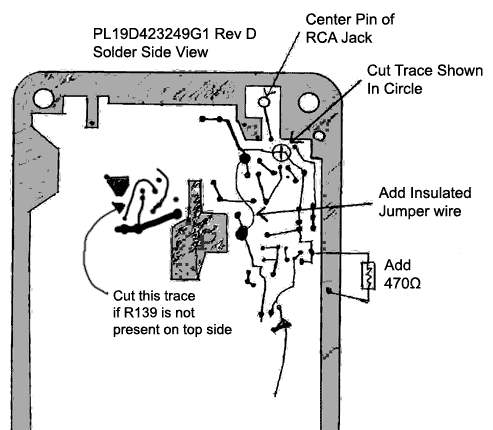
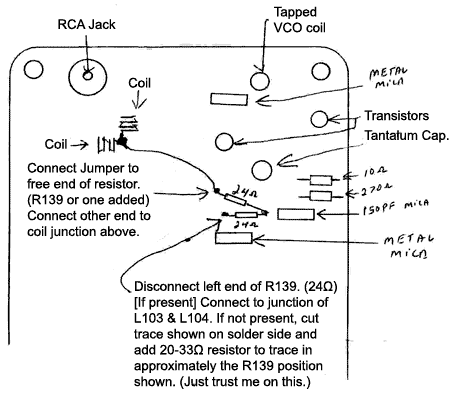
These additional instructions are for NON 'Rev-K' exciters. These instructions change the phase detector's sampling point from the VCO directly, to the buffer stage after the VCO. They also change the powering of that buffer stage so it is powered at all times. The powering also allows for the final stages to be activated only when the VCO is locked on frequency. The hand-drawn illistrations are for reference only. As with any modifications, it is ALWAYS best to have a full printed manual for the equipment that is being converted.
 |
 |
Copyright© June 07 2000. Rob Mang K2ROB
HTML Copyright© June 07 2000 Kevin Custer W3KKC
Additional notes from Rob Mang added March 15 2007 by N3XCC
All Rights Reserved.