|
Up one level Back to Home |
Repair and Overhaul of the Daniels UHF Receiver Front End By David VanHorn KC6ETE |
Well that was fun...
You know how one thing leads into another?
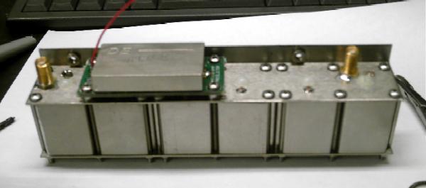
I was just in doing some pictures of the Daniels 440 MHz Receiver for the receiver article, when I thought to myself, that I ought to go ahead and retune this one. At least retune the input filters since I don't have the crystals yet and I can't do the IF chain.
Well, I dismounted the filter, and started on the tuning, and I noticed that the first can, on the antenna end, had a loose trimmer capacitor. In a Daniels receiver that's very bad news. Worse, the little wire coming out of it was loose, indicating that it had been rotated hard enough to break that wire. Well, since the filter was already broken, I decided to do a field strip and repair, and along the way, document the whole process. Normally, I wouldn't touch the internals of an assembly like this, but with the filter broken as it was, I figured I had nothing to loose.
First, you need to disconnect the filter module from the receiver, which is just a matter of four screws, two SMA connectors, and the red wire where it solders to the end of a diode.
Now, you can undo the solder connections on either end of the shield over the pre-amplifier, and unsolder the two coax leads from the cans to the amplifier and straighten the center conductors, because you'll need to slide them through the board when you remove it.
Now carefully desolder the coax shields from the amplifier board ground. Solder wick (or coax braid dipped in flux) will help here. Fortunately, the coax uses a Teflon dielectric, and is relatively immune to heat.
Now undo the four screws in the corner, watch the washers and spacers, and slide the amplifier board off. Lay it, and all of the hardware aside. You now have the topside of the filter assembly with the amplifier removed.
Now, DO NOT UNDO THE NYLON SCREWS! They hold the resonator forms in place. There is no need to mess with these.
Go to the other side, and unsolder the three pairs of cap wires, making sure that the wires are clean, because you will need to thread them through the small holes they come through.
Remove the covers from the tuning caps, if you haven't already.
Remove all the metal screws, nuts and washers from the topside.
Now carefully undo the nuts and washers on each of the six tuning capacitors. Be very careful that you DON'T rotate the capacitor bodies, you'll see why in a minute. Keep careful track of those very tiny washers.
Gently bend the cap wires up till they point straight up.
Lift the bottom cover off the assembly.
If you remove the can bodies at this point, keep careful track of which are which, and which end points toward the input side. They are almost identical... key word being "almost".
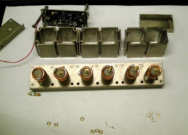
Now you will see why you need to be so careful with the capacitors. They are connected to the resonator by a fairly fine wire (28 or 30Ga) which is easy to snap. In my case, whoever worked on this module previously had already snapped the wire.
To repair mine, I set the capacitor in place, and resoldered the wires, very carefully.
Re-assembly is pretty much just the reverse of the above.
When you are putting the washers and nuts back on the tuning capacitors, it helps to put the jeweler's screwdriver through them, and then use the screwdriver as if to tune the caps, allowing the washer or nut to fall into place down the shaft of the screwdriver. This way, the cussed little parts have no real option except to go where you want them to go.
When you get to the point of putting back the housing screws, do the four under the amplifier first, and tighten them completely, because you won't be able to once the amp is mounted.
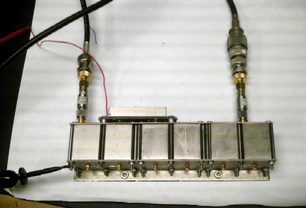
When you have completed re-assembly, you'll need to re-tune. I took pictures of where my filter was before we began the disassembly, and then again after retuning. A very nice repair indeed and a fully functional filter again.
Tuning:
The VHF and UHF filters differ only slightly, and the procedure is pretty much the same. The VHF version simply has fewer stages to tune.
You'll need a spectrum analyzer to cover the proper range, with a tracking generator. A power supply adjusted to 9.5V and capable of at least 50mA output is required, to power the pre-amplifier. You could probably use a fresh 9V battery.
A small jeweler's screwdriver to adjust the trimmers, and a larger one to remove the trimmer covers.
Ideally, a pair of SMA 3 dB or 6 dB pads, but you can live without them.
You'll also need the appropriate cables and adapters to connect to the filter's female SMA connectors.
I use an HT as a marker generator, just key up on the appropriate frequency to get a "pip" on the spectrum analyzer, which I center in before I start adjusting.
Find where the filter is currently set, and where you want to go, and get them both on the screen at once, if possible. You'll want to slide the filter's passband up, taking all of the cans together in small increments.
Remove the trimmer covers, and set them aside.
When tuning, go very slowly, maybe 100-500 kHz at a time on any adjustment, about 1/8 of a turn. Turning the trimmers counter-clock-wise increases the pass frequency, and clockwise lowers it.
Walk end to end, then back down, progressively sliding each stage toward the desired frequency.
When you think you have it dialed in, go to 2 dB/Division, and rock all the trimmers for best pass gain at the desired frequency. If you significantly change one, then try its neighbors on each side.
In the end, you should have a response pretty much like what I show in the final picture, and you're ready to tune the crystal oscillator and LO multiplier chain.
Replace the trimmer covers, and optionally, lock them with Locktite or some nail polish in a color your wife didn't like. I got some flaming orange this way, and one bottle lasts me years! She seems to use a lot more for some reason...
Re-install the filter, in the case, and don't forget to solder the red wire back to the diode where it was originally attached.
You're done. Go have a nice tall glass of your favorite beverage.
Back to the top of the page
Up one level
Back to Home
Text © Copyright 2005 by David VanHorn KC6ETE
Hand-coded HTML © Copyright 2005 Mike Morris WA6ILQ
The information presented in and on these conversion pages is © Copyrighted 1995 - (date of last update) by Kevin Custer W3KKC and multiple originating authors.