Back to Home
Switching Transients
By Robert W. Meister WA1MIK

|
Backup Power index Back to Home |
Line-Interactive UPS Switching Transients By Robert W. Meister WA1MIK |

|
Background:
APC (American Power Conversion Corp.) manufactures several lines of consumer-grade Uninterruptible Power Supplies (UPS). This particular test was performed on one of my SU-1000 models, which is capable of supplying 1000 watts or 670 VA for up to 20 minutes depending on the load current and the condition and/or age of the internal batteries.
UPS units come in several configurations. For normal consumer-grade devices, two major styles are described below:
Some inverters provide sine-wave output while others provide a modified square-wave output. Either type of UPS can also contain a tapped transformer that can boost the output voltage during a brownout, or lower the output voltage if the input should become excessively high, by a fixed amount. These switch points are usually adjustable. Other models may contain a ferro-resonant transformer for voltage regulation. Some models can accept an external battery pack to offer extended run-time.
The SU-1000 has a sine-wave output. It is line-interactive and contains several relays to switch the load and inverter. A pair of 12V, 7AH batteries inside are used to run its inverter. When the incoming AC goes away, there is a short transient in the load voltage when the relays switch the output to the inverter. This article documents that brief momentary loss of power.
Test Setup:
I connected the "A" channel of the scope to a line cord plugged into a two-way splitter, which also fed the UPS. This is seen as the red or upper trace in the waveforms below. This allowed me to pull one plug from the wall to disconnect AC power from both the UPS and the scope.
I connected the "B" channel of the scope to the output of the UPS, which also fed the 60w table lamp as a load for the UPS. This is seen as the blue or lower trace in the waveforms below. Both channels were set to the same scale of 100 volts per division. I oriented the plugs to get both signals in phase. The diagram below shows how the equipment is connected:
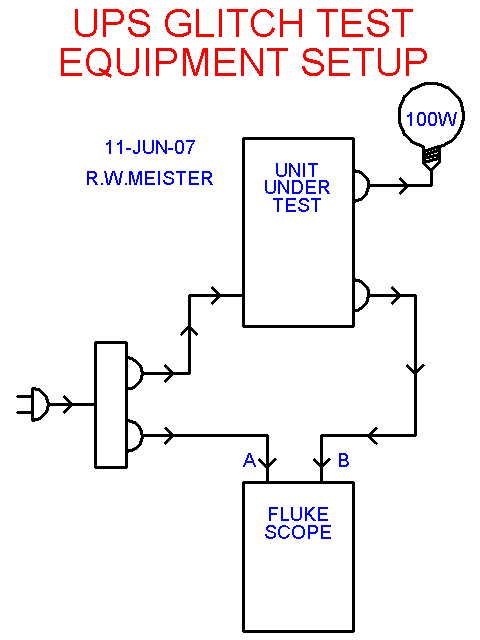
The scope trigger was set to detect any pulse on channel "A" that was not equal to about 8.2 milliseconds. The intent was to catch the point when the input AC power was removed. The horizontal time is 10 milliseconds per division. At 60 Hz line frequency, one cycle takes 16.6667 milliseconds or 1.6667 divisions. Three full cycles takes exactly 5 full divisions on the scope.
All I had to do was pull the plug from the wall and record the waveforms where the interruption was present in the middle of the trace.
Test Results:
It did seem as if the results were somewhat random as far as triggering the scope was concerned. However, I did get several easily viewed events, shown below.
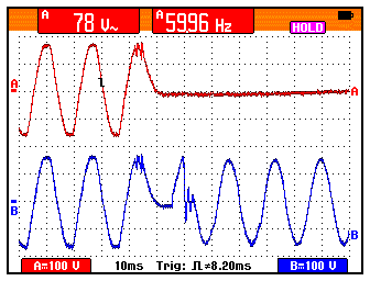
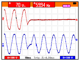
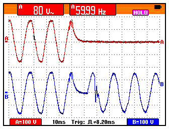
The actual switching time seems to be between 10 and 30 milliseconds. Notice that the incoming AC (red trace) and the outgoing AC (blue trace) prior to the plug being pulled are a bit distorted - the peaks are slightly flattened. Once the UPS inverter takes over and provides the output voltage, the outgoing AC (blue trace) looks a lot better. Also, the outgoing AC waveform seems to be exactly in phase with the incoming AC waveform after the plug has been pulled. One or two cycles of bad power are the only indication something's happened, and most modern electronic devices won't notice it. If you have one that does, there are usually ways to modify it so that it rides through this minor glitch.
Since the supply voltage is connected directly to the load, any glitches or other noise will be fed through to the load until the UPS inverter takes over. Switching transients are not handled well by this style UPS. They work well for a simple outage where the supply cleanly fails, stays off for a while, then returns.
Note that on a true on-line UPS, there would be no switching transient on the outgoing AC waveform since there are no load-switching devices inside the UPS.
Another UPS Tested:
I bought a TrippLite Smart1000LCD but received an Omni1000LCD and immediately returned it (TrippLite recalled all the Smart1000LCD models due to overheating and possibility of fire, but I can't find anything about this any more, except I wasn't the only person who mentioned it). This unit has a very rapid switching time, according to the specs: "Transfer time from line power to battery mode: 2-4 milliseconds". I connected this unit in place of the APC unit and ran the same test. Here's the resulting switching waveform:
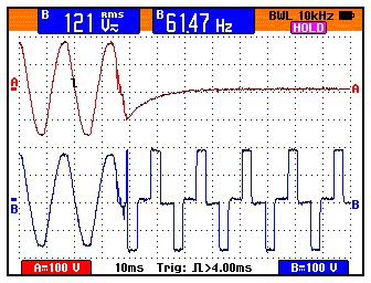
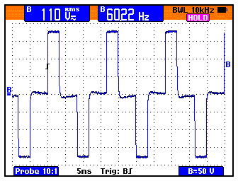
This unit does switch to the inverter a lot faster than the APC unit does, however the output waveform is a single step sine wave approximation. I suppose the pulse width is widened as the load increases, but it's certainly not what I had expected. The specifications report "BATTERY MODE: PWM sine wave 115V +/-5%, Inverter output regulated to 60Hz +/-0.5Hz". This is what the output waveform looks like and measured:
Contact Information:
The author can be contacted at: his-callsign [ at ] comcast [ dot ] net.
Back to the top of the page
Backup Power index
Back to Home
This page written 11-Jun-07 and first posted 23-Dec-07
Photographs, article text, and hand-coded HTML © Copyright 2007 by Robert W. Meister WA1MIK.
This web page, this web site, the information presented in and on its pages and in these modifications and conversions is © Copyrighted 1995 and (date of last update) by Kevin Custer W3KKC and multiple originating authors. All Rights Reserved, including that of paper and web publication elsewhere.