Back to Home
Converting an APC Smart-UPS to an APC Smart-UPS XL by Installing Larger Batteries
By Robert W. Meister WA1MIK

|
Backup Power index Back to Home |
Extending Smart-UPS Run-Time Converting an APC Smart-UPS to an APC Smart-UPS XL by Installing Larger Batteries By Robert W. Meister WA1MIK |
|
The APC (American Power Conversion) Smart-UPS SU1000NET is a fairly robust, intelligent Uninterruptible Power Supply (UPS). It is rated for 1000VA or 680 watts. The normal battery pack (RBC6) consists of two 12V, 12AH Sealed Lead-Acid (SLA) batteries stuck together with double-sided foam tape. The pack is 3.75 inches tall by 6.00 inches wide by 7.75 inches deep. The batteries are wired in series with a 32V, 60A Buss Maxi-Fuse that's usually stuck to the top of the pack with double-sided foam tape. 1/4 inch quick disconnects are used on all connections, although my pack has 3/16 inch terminals. At full load, these can provide about 6.1 minutes of run-time.
My unit operated for about five years on its current set of batteries. Since I had to replace them anyway, I decided to go with a larger capacity pack. The SU1000XLNET unit uses 12V, 18AH batteries which are quite a bit bigger. Each one is 6.57 inches tall by 3.00 inches wide by 7.13 inches deep, and the terminals are thick, upright ,and have holes in them. Lug-style connectors are normally used with these batteries. A pair forms a pack (RBC7) which is 6.00 inches wide. Run-time on this unit is about 9.6 minutes at full load.
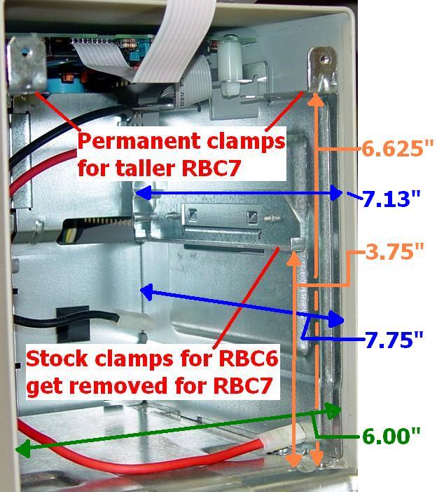
The space available for RBC6 battery packs is 6.00 inches wide by 7.75 inches deep. Height to the stock battery hold-down clamps is 3.75 inches, but without them you have about 6.625 inches at the outer edges of the cabinet; more height is available in the middle under the circuit board, and the batteries need to be installed so the fuse and leads are in the center. The RBC7 pack is 6.00 inches wide and should fit snugly into the chassis. Metal stops at the rear of the side panels accommodate the RBC7's shorter depth.
I subsequently performed this same modification to an APC SUA1000, which seems to use the same chassis parts. All references to the SU1000 also apply to the SUA1000.
CAUTION: Before working on your unit, unplug the AC power cord, disconnect and remove the old battery pack, and attempt to turn the unit on several times to fully discharge the internal capacitors. Potentially lethal voltages are present inside the unit.
You can click on any photograph below to see a larger view.
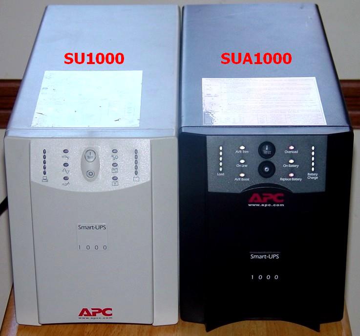
Here's a front view of the SU1000 and SUA1000 units:
Removing the Old Pack:
The batteries are accessed by unsnapping the front panel and removing two screws that hold the metal cabinet front in place. The battery pack may then be slid out and replaced with the same size while the unit is operating on AC power (hot-swappable).
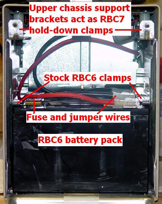
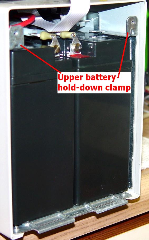
The original battery is held in place by two hold-down clamps inside the left and right sides of the chassis. It fits underneath the rear stops which are used for the RBC7 pack. The RBC6 pack slides all the way to the rear of the chassis, under these stops.

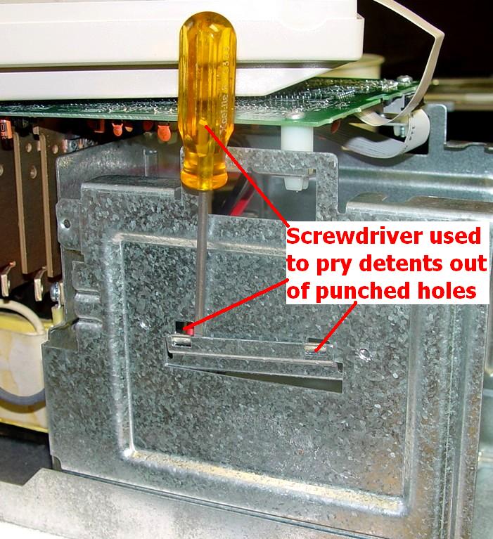
After the battery pack is removed, you can better see the two clamps:
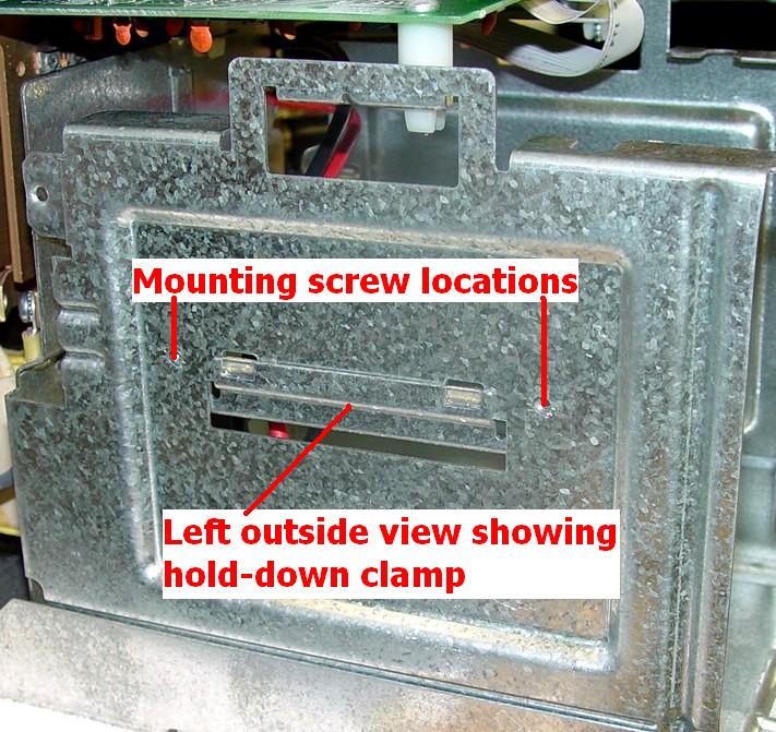
These clamps are held in place with two small screws from outside the chassis, under the protective metal cover. Flip the unit over and remove the six Phillips-head screws along the outer edge of the cover. Flip the unit back on its feet and slide the cover off towards the rear of the unit. Remove the two small screws holding the clamps in place, then use a screwdriver to pry the clamps out of the knockout slots. Put the screws into the clamps and store them in case you ever need to convert the unit back to stock.
The inside of the chassis is now prepared to accept the larger batteries. The brackets at the top of the chassis, under the circuit board, are at the proper height to hold the RBC7 battery pack in place. You can now replace and secure the top cover onto the chassis.

Installing the New Pack:
I purchased one pair of batteries to make my RBC7 pack. Some dealers sell a real pack composed of two batteries joined by double-sided tape; this may also come with a new fuse. I went the cheap way, buying separate batteries and reusing the old fuse. I did not join the two batteries together, but I do recommend using either some double-sided foam tape between the cells or a couple of wraps of cellophane packing tape around them. This just makes insertion and removal a bit easier.
The SU1000NET uses 1/4 inch quick disconnect female terminals on the end of the black and red battery wires, as well as the fuse jumpers (the fuse has 5/16 inch terminals so they often come with short wires to let it mate with the battery terminals). These mate with 1/4 inch male terminals on the RBC6 batteries.
The RBC7 batteries I bought had thick lugs with holes in them. Other batteries may vary. I used some #10-32 machine screws, flat washers, and nuts. I suspect that a real SU1000XLNET has an appropriate disconnection method and probably wires a different style fuse directly to the battery lugs.
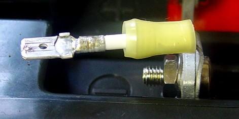
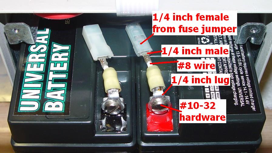
I made four short (1 inch) jumpers using some #8 Teflon-insulated silver-tinned stranded wire. One end has a 1/4 inch quick disconnect male terminal to mate with the SU1000NET's battery and fuse wires, while the other end has a 1/4 inch round lug terminal. Each connection was crimped and soldered. If you can find 5/16 inch quick-connect female terminals, you can use two of these to mate directly with the fuse and do away with the short jumpers that were used to attach it to the old pack. Here's a close-up of one of these:
and here's what the top of the batteries look like with the fuse installed:
I attached one short adapter to each battery terminal. Then, I started inserting the left battery into the chassis with the terminals towards the center of the UPS. I attached the red wire from the UPS to the adapter on the positive (red) terminal of this cell. I started inserting the right battery into the chassis, also with its terminals towards the center of the UPS. I attached the black wire from the UPS to the adapter on the negative terminal of this cell. Wire clearance does not seem to be a problem as there's plenty of room for them behind the batteries, but I did try to keep them above the top of the batteries as I slid them in. With about two inches to go, I attached the old fuse to the remaining two terminals of the battery. There WILL be a healthy spark when you make that final connection; this is normal. I now use a 22 ohm 2 watt resistor in series with the final battery terminal and UPS lead to charge the UPS capacitors before making that final connection; no more spark.
CAUTION: Make sure you double-check that the polarity and color of the epoxy around the battery terminal matches the color of the wire going into the UPS. It's just as easy to make the connection incorrectly (been there, done that - ONCE - it's not pretty).
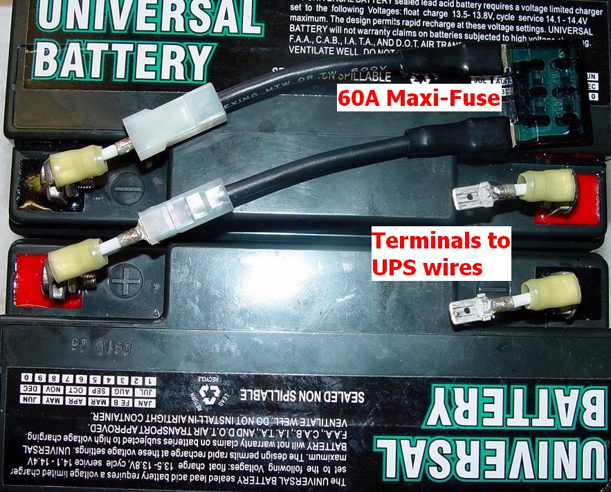
Another alternative is to cut the existing quick-disconnect connectors off everything and attach the proper size single-hole crimp lugs to the fuse and power wires. Yellow insulated lugs for #10 and #12 wire and #10 screw holes will work fine. The photo below shows a unit with new crimp-on lugs, and the batteries were taped together. Mike WA6ILQ provided this photo of a unit he converted recently:
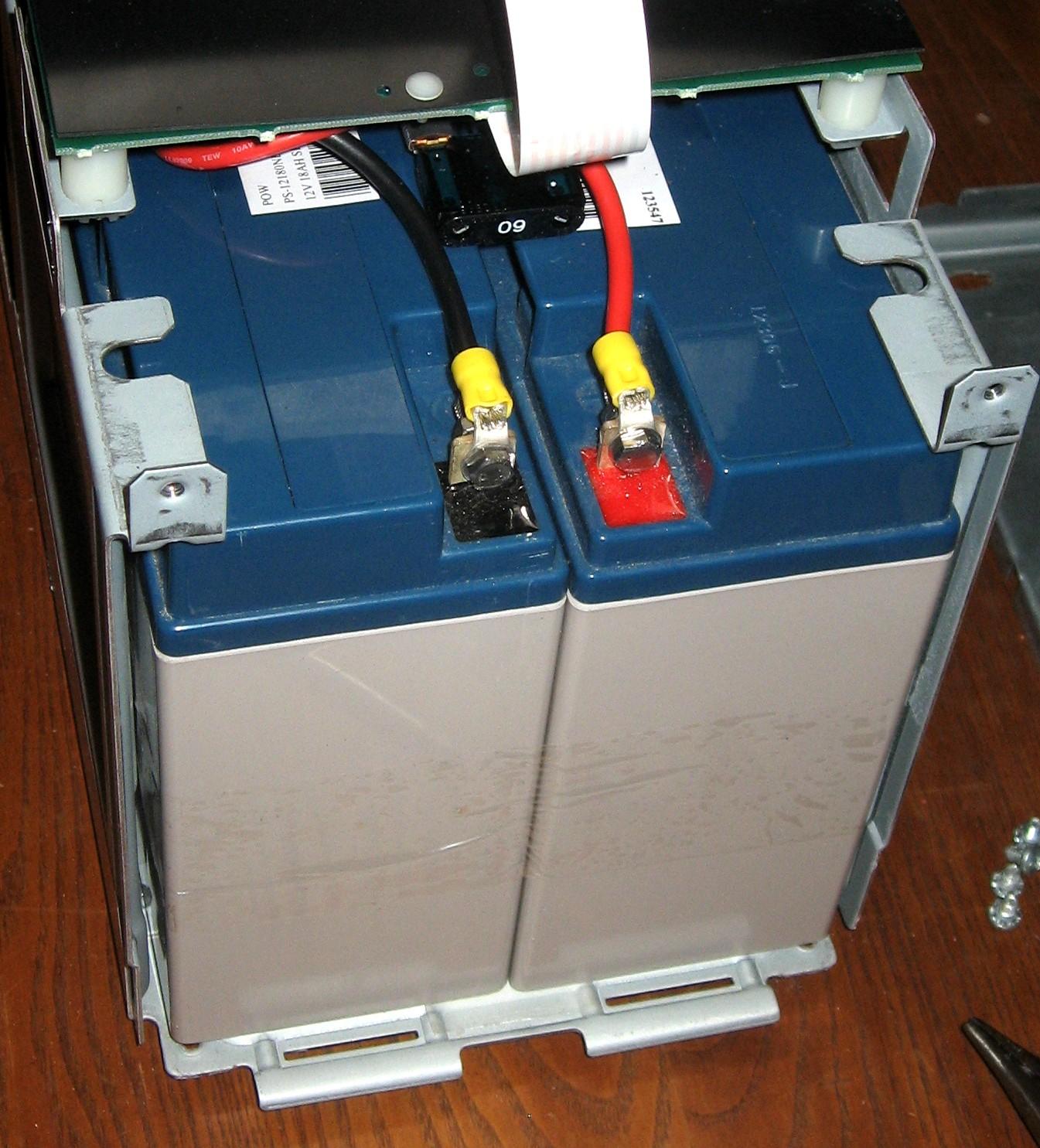
The photo below shows the outer end of the RBC7 batteries; the terminals at this end are connected to the fuse. The opposite end of the pack is connected to the SU1000's red and black battery leads. You can insert the pack either way. I subsequently put the fuse end in first and attached the power leads after the batteries were inserted half-way into the unit. Just make sure they don't get caught by other flat cables inside the UPS. I also wrapped the exposed parts of the fuse blades with black electrical tape.
Carefully slide the entire pack into the chassis. Movement will stop when the batteries reach the rear stops, visible in one of the photos above. As you can see, they fit exactly into the available space:
Put the front door back onto the chassis, secure it with two screws, and reattach the front panel. Plug the unit in, check for normal operation, and let it charge for 24 hours. As this pack is larger than normal to provide extended run-time, the recharging and recovery times will also longer. Recharging time for the original SU1000NET is 3 hours, 5 hours for the SU1000XLNET.
NOTE: It is a good idea to add notes on the UPS indicating that the battery capacity has been modified, to make it easier for the next person who has to replace the batteries. I'd suggest adding such a note on the front cover, on the metal battery cover behind the front cover, on the top cover, and on the rear panel.
Other Information:
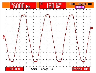
While I had the unit on the bench, I hooked my oscilloscope to the AC output. Here's the waveform coming from the line. Note there is considerable flattening of the waveform peaks:
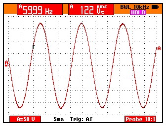
Now it's running on the battery. This shows about 1% total harmonic distortion with no load:
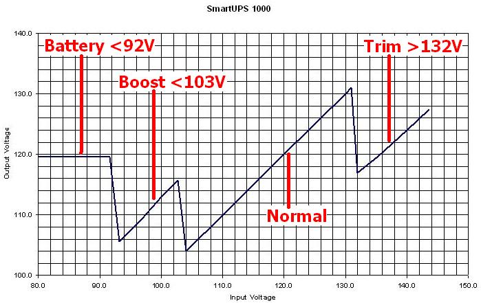
I also plugged the unit into a variable AC source and noted the input and output voltages. This unit will trim the output voltage by about 10% if the input goes above 132VAC, and it will boost the output voltage by about 12% if the input goes below 103VAC. It switches to battery if the input goes below 92VAC input. This graph shows the various switching points:
A reader sent me information and a link to some Sealed Lead-Acid (SLA) battery terminal adapters. They let the battery's nut/bolt terminals accept F2 (1/4 inch) push-on connectors. There are other useful adapters here too.
Acknowledgements and Credits:
APC, Smart-UPS, SUA1000, SU1000NET, and SU1000XLNET are trademarks of American Power Conversion Corporation.
Buss and Maxi-Fuse are trademarks of Cooper Bussmann Automotive Products.
Teflon is a trademark of E. I. du Pont de Nemours and Company.
The 12V, 18AH batteries (used to make the RBC7 pack) were purchased from Gruber Power Services of Phoenix, Arizona, via an on-line auction. Do NOT provide this company with your e-mail address (they got mine from winning the auction). They automatically add every one to their SPAM database. Weekly unsolicited messages start coming in, and asking to be removed does nothing (of course). Their products and services seem to be top-notch, but their marketing strategies are to be avoided at all costs.
All photos were taken by the author unless otherwise noted.
Contact Information:
The author can be contacted at: his-callsign [ at ] comcast [ dot ] net.
Back to the top of the page
Backup Power index
Back to Home
This page written 20-Dec-06 and first posted 23-Dec-2007
Photographs, article text, and hand-coded HTML © Copyright 2007 by Robert W. Meister WA1MIK.
This web page, this web site, the information presented in and on its pages and in these modifications and conversions is © Copyrighted 1995 and (date of last update) by Kevin Custer W3KKC and multiple originating authors. All Rights Reserved, including that of paper and web publication elsewhere.