Back to Home
Arcom RC-210 Repeater Controller
By Randy Elliott VE3JPU
|
Up to Arcom index Back to Home |
Interfacing a Weather Alert Radio to the Arcom RC-210 Repeater Controller By Randy Elliott VE3JPU |
|
This article describes how I interfaced a Reecom R-1630C S.A.M.E. (Specific Area Message Encoding) Digital Weather / Hazard Alert Radio to the Arcom RC-210 controller. Both a Programming Guide and a User's Manual for this unit are available on-line.
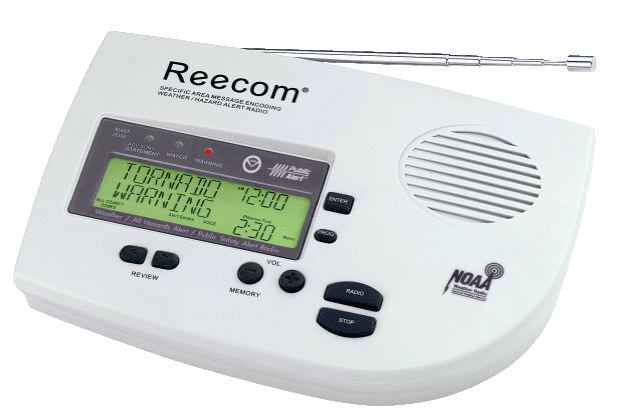
The Reecom R-1630C radio is very simple to operate and program. It has rear panel jacks for external antenna, external power, Audio Out and Alarm Out signals. Both output jacks are 1/8 inch (3.5mm). The Audio Out level is controlled by the front panel controls.
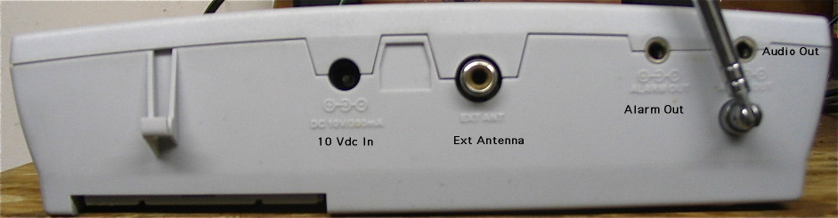
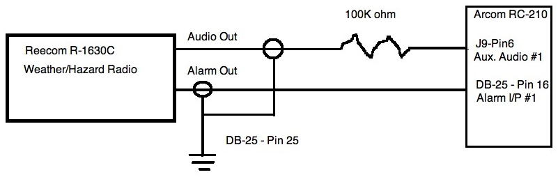
Several Alarm Out signal configurations are possible. When a weather alert is received, the Alarm Out signal can provide a 6 volt DC output or a contact closure, with maximum electrical ratings of 12 volt DC and 350 mA. I set the R-1630C for the contact closure mode, wired it as a contact closure to ground, and I programmed the RC-210 for falling edge triggering.
The Arcom RC-210 Repeater controller has provisions for three Auxiliary Audio input signals as well as five Alarm inputs. These alarm inputs can be programmed for rising or falling edge triggering. Each condition invokes its own designated macro.
Because the R-1630C radio has its own alert siren tones, I chose not to program any kind of voice announcement into the RC-210 but used the triggering macro to connect the audio from the weather radio to our VHF and UHF repeater transmitters. I then have the Auxiliary Audio timeout timer programmed to disconnect Auxiliary Audio #1 from both transmitters (ports 1 and 2) after about 90 seconds. After trial and error I found this to be enough time to allow the weather warning to be broadcast in its entirety.
The connection to the RC-210 controller was very straight forward. Because the RC-210 does not have any means to control the audio level of these auxiliary inputs, this must be done externally between the weather radio and the RC-210, hence the 100k resistor in series with the audio line.
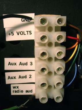
J9 is a six-pin header located on the main PCB of the RC-210. To make connections easier, I brought this header connection out to a terminal strip mounted to the rear of our RC-210 rack mount enclosure.
You will have to look in the RC-210 manual for programming and configuration information, as there are lots of variables, but here is a list of things to remember:
And that's about it!
Contact Information:
Randy Elliot is Technical Director of the South Pickering Amateur Radio Club Inc.
He can be contacted at ve3jpu [ at ] rac [ dot ] ca
Back to the top of the page
Up to Arcom index
Back to Home
This page originally posted on Saturday 27-Dec-2008
Article text, images, drawings, and artistic layout © Copyright 2008 by Randy Elliott VE3JPU.
Conversion to Repeater-Builder format and HTML by Robert Meister WA1MIK.
This web page, this web site, the information presented in and on its pages and in these modifications and conversions is © Copyrighted 1995 and (date of last update) by Kevin Custer W3KKC and multiple originating authors. All Rights Reserved, including that of paper and web publication elsewhere.