Up to ACC index
Back to Home
By Darrin Stanley KB6WAS
This web page was developed by Mike WA6ILQ from an email
Thanks go to Darrin for permission to present his work.
|
Up to Arcom index Up to ACC index Back to Home |
Installing an Arcom Digital Audio Delay board into any ACC Controller By Darrin Stanley KB6WAS This web page was developed by Mike WA6ILQ from an email Thanks go to Darrin for permission to present his work. |
|
Notes from the Editor (WA6ILQ):
The repeater controllers made by Advanced Computer Controls are fine controllers, but are
old enough that many parts are no longer available. One is the SAD4096 audio delay
line chip (the so-called "bucket-brigade" chip), which has been out of production for
years and nobody has any in stock. The simple solution is to replace it with a
coupling capacitor, but you will end up without any delay. The better way is to
replace the old dead or dying ACC audio delay with
a new Arcom
digital delay board (at about US$50), which is more flexible (the delay can be from
8ms to 2 seconds), has better signal-to-noise performance, a bunch less audio distortion,
and best of all, it drops right in.
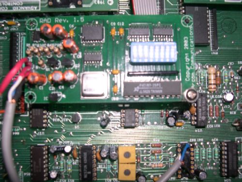
From: Darrin Stanley KB6WAS Date: Mon, 27 Aug 2005 Subject: Re: ACC audio delay replacement Hooking up the "RAD" audio delay board to an RC-850 is rather simple: Hook pin 1 of RAD to a source of clean +12 volts DC. Hook pin 2 of RAD to pin 6 of U35 (where the audio delay chip used to be). This is audio in. Hook pin 3 of RAD to pin 16 of U35. This is delayed audio out. Hook pin 4 of RAD to pin 9 of U35 (ground) or to the closest circuit board ground. You do not have to hook up the COS signal to the RAD if you are sending it audio that is already squelch muted. RAD board pinout: pin 1 = Filtered +12 volts DC pin 2 = Audio in pin 3 = Delayed audio out pin 4 = Ground pin 5 = COS (optional - if not used connect this pin to ground) RC-850 U35 pinout (only two pins plus ground are used): pin 6 = to the RAD audio input pin pin 16 = from the RAD delayed audio out pin See the photo of how I installed it using the same standoff that was used for the original ACC Audio Delay Board. The RAD board is DIP switch programmable, and the manual is on the Arcom web site. The configuration that I found was the closest to my ACC delay board are switches 1-5 = on, and 6-9 = off. |
Some notes from the Editor (WA6ILQ):
Back to the top of the page
Up to Arcom index
Up to ACC index
Back to Home
Original text (the white background) © Copyright 2005 Darrin Stanley KB6WAS
Comments, artistic layout and hand-coded HTML © Copyright 2005 and date of last
update by Mike Morris WA6ILQ
This page last updated 20-Dec-2005
This web page, this web site, the information presented in and on its pages and in these modifications and conversions is © Copyrighted 1995 and (date of last update) by Kevin Custer W3KKC and multiple originating authors. All Rights Reserved, including that of paper and web publication elsewhere.