Home page
for 2-meter Amateur Use
By Kevin K. Custer W3KKC and
Robert W. Meister WA1MIK

|
Antenna Index page Home page |
Modifying Wacom VHF Duplexers for 2-meter Amateur Use By Kevin K. Custer W3KKC and Robert W. Meister WA1MIK |
|
Background:
There are a lot of Wacom VHF duplexers available on the surplus market, but, unless they were built originally for 2M, they likely have the wrong notch stub geometry to work correctly in the 2M ham band. While the pass-band cavities will generally tune to the 2M band by winding down the threaded rods, many of these surplus VHF duplexers were built for splits greater than 600 kHz. The design of the notch stubs seriously limits the tuning range of the notch adjustment. As such, modification of the notch rods might be necessary to make them accommodate a 600 kHz TX to RX spacing. This modification generally involves (at least) altering the center conductor length. The center conductors are made of brass pipe, which originally was silver-plated. In some rare instances, the Rexolite® notch rods may need to be line bored deeper to accommodate a longer center conductor.
Duplexer Configuration:
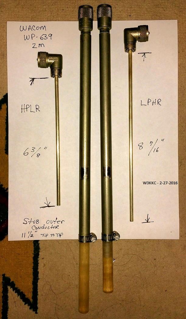
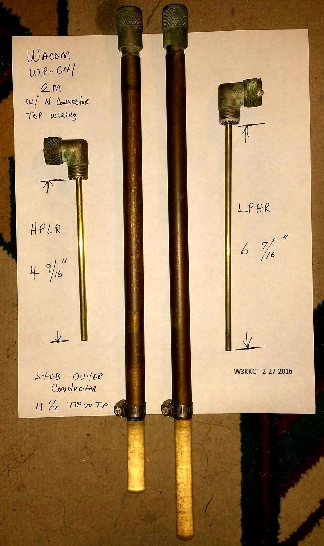
The WP-639 duplexer consists of four 5-inch cans. It covers the 2M band and can do 600 kHz spacing minimum if it was ordered that way. The WP-641 duplexer consists of four 8-inch cans. It covers the 2M band and can do 500 kHz spacing minimum if it was ordered that way. Of the two, the WP-641 has slightly better specs.
Both of these are pass/reject duplexers, where the main cavity handles the pass-band tuning while a stub hanging off the side of the cavity handles the reject-band tuning. The spec sheets as well as tuning instructions can be found in the Wacom duplexer section on the Antenna Systems page on this web site.
Modifications:
Here are photos showing factory 2M notch stubs for the WP-639 duplexer. Click on any big photo for a larger view.
Here's a photo of the factory 2M notch stubs for the WP-641 duplexer.
One final photo shows the notch stub for a WP-639 that was originally built for the mid-150 MHz band with 6.5 MHz TX to RX frequency spacing.
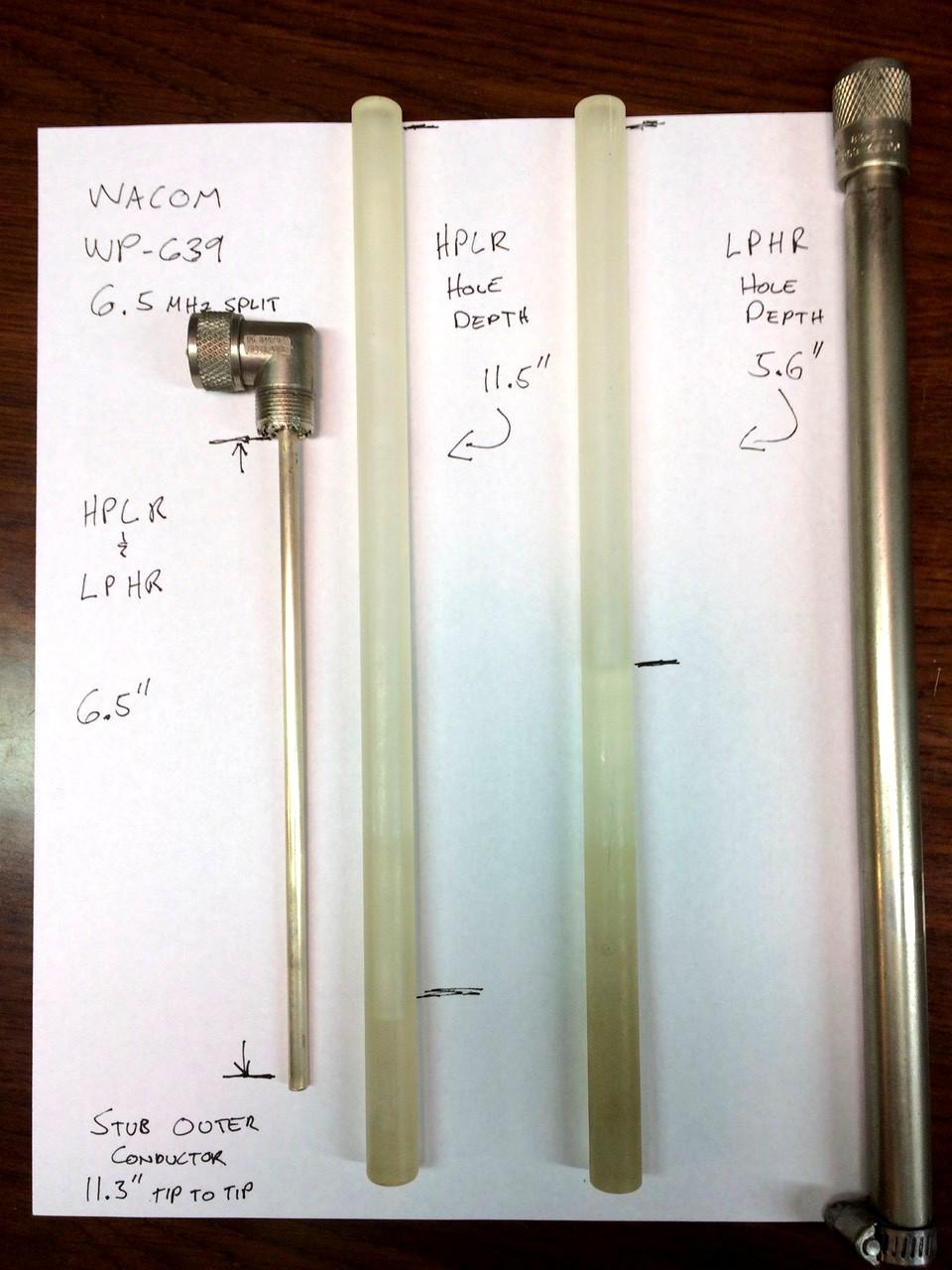
To convert this duplexer, one set of notch stubs needed to have their center conductors lengthened, while the other two were fine as is. This particular duplexer had one set of Rexolite rods that were already deep enough to accommodate the lengthened center conductor rod. An extension was soldered onto the existing center conductor's brass pipe to lengthen it. The joint was strengthened by using a smaller diameter pipe inside at the joint, which extended about an inch inside both outer pipes. (You could also use a piece of solid material inside the pipe.) It doesn't appear that silver-plating the extension is necessary, as long as it's bright and shiny. You can polish it up and spray it with a thin coat of clear lacquer to keep it that way.
Specific Details:
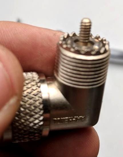
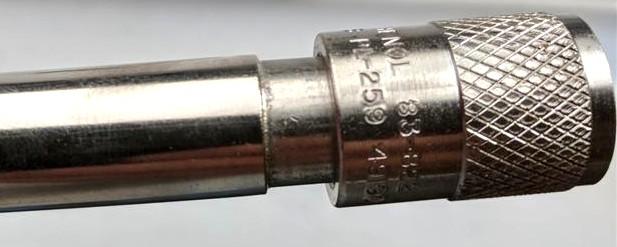
The right-angle adapters are critical. I've seen people substitute Chinese adapters and then not be able to make the duplexer perform correctly. They must be genuine Amphenol UG-646/U adapters, part number 83-1AP, specially modified. Here's a photo of the adapter taken apart.
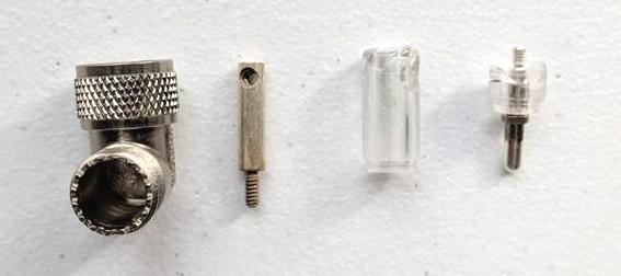
This piece was either manufactured for, or by, Wacom. I've owned many of these duplexers for 2M and 222 MHz and they are all made this way. Note that the female end has been replaced with a male threaded end. The inner brass rod has been fitted with a female threaded end, which screws onto the male end of the elbow. If the elbow gets broken (which I've accidentally done) only the outside casting gets ruined. The guts can be removed from the original elbow and installed into a replacement. Here's a photo of the modified elbow with the threaded end.
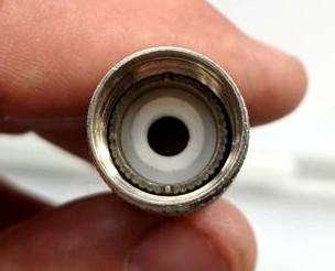
This female threaded end attaches to the brass rod that fits inside a Teflon PL-259 male connector whose center pin has been removed. Here's a photo showing the modified PL-259.
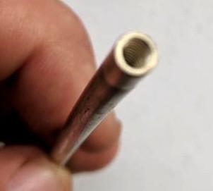
And here's a photo showing the end of the brass rod.
The outer tube of the notch tuning assembly is a piece of brass pipe selected to fit over the PL-259 inner body. It is 0.553 inches OD and .500 ID. Here's a photo showing where it attaches to the PL-259.
The inner conductors measures 0.1865 inches OD, and its length determines the basic capacitance. The diameter of the hole in the Rexolite rod measures .190 inches, but is tough to accurately measure with an inexpensive caliper using its inside measuring jaws. My calipers inside jaws are too large to totally fit inside the hole. The end of the rods inside hole is slightly chamfered to aide in centering the free end of the inner conductor when starting the rod. While the outside of these stubs are approximately a foot long - the inner conductor is much shorter and without the slight chamfer starting the rod where it eventually meets the inner conductor would be increasing difficult.
All tubing / pipe is silver-plated. The outer one has four notches cut in the bottom end so a hose clamp can be used to compress the tube onto the Rexolite rod, which is 0.500 inches OD and is a snug fit inside the larger pipe. This forms an adjustable capacitor that's very stable mechanically and electrically, and has a slim chance of arc-over when/if hit by lightning. The length of the outer tube is not important, as long as it's longer than the internal tuning rod embedded in the Rexolite.
The holes in the Rexolite rods can vary in depth. I've always lucked out, having two rods that were drilled deep enough to accommodate the lengthening of the conductor. I don't know if Wacom supplied their duplexers with one set of long and one set of short drilled rods, but that's what I've always encountered. I have never had to drill out the rods, but I've heard of others that have had to.
Credits and Acknowledgements:
The WP-639 6.5 MHz spaced stub photo was provided by Cort Buffington NØMJS.
All other photos were taken by the author.
Contact Information:
The author can be contacted at: kuggie [ at ] kuggie [ dot ] com.
Back to the top of the page
Back to Antenna Index page
Back to Home
This article created on Saturday 04-Aug-2018
Article text and photographs © Copyright 2018 by Kevin Custer W3KKC.
Layout and conversion to HTML © Copyright 2018 by Robert W. Meister WA1MIK.
This web page, this web site, the information presented in and on its pages and in these modifications and conversions is © Copyrighted 1995 and (date of last update) by Kevin Custer W3KKC and multiple originating authors. All Rights Reserved, including that of paper and web publication elsewhere.