Antenna Index page
Home page
Losses
By John Portune W6NBC

|
Book Index page Antenna Index page Home page |
Cavity Duplexers Chapter 8 Losses By John Portune W6NBC |
|
This is undoubtedly the most important chapter. It contains the hidden secrets. Wrapped up here are the major compromises that create optimum performance with maximum economy. We'll talk about energy transfer, skin effect, cavity proportions, and most important of all, bandwidth vs. insertion loss. These are vital concepts.
Energy Transfer:
How does energy, our receiver or transmitter signal, get into and out of a cavity? It works the same way for all cavity types: Bp or Br. Energy enters from an input transmission line most often via an input loop. The loop, for all practical purposes is just a small inductor. It is more complicated then that, but this is an adequate approximation.
The magnetic field around the loop excites the cavity into oscillation. As we said earlier, it is like blowing air across the top of a soft drink bottle. In so doing, the cavity absorbs the energy delivered to the loop by the input transmission line. At the output loop, provided it has been configured to have the same performance as the input loop, the complement takes place. The energy returns to the transmission basically unchanged, little is lost except for that which we don't want.
Said in simpler terms, what goes in at the frequency we want comes out. Said another way, a cavity should essentially be invisible to energy passing by at the resonant frequency. At other frequencies, however, the losses are made as high as we can. That is the basic idea of a cavity filter - keep the good stuff, get rid of the junk.
But unfortunately cavities are not perfect. They always lose a little of the good stuff even at the resonant frequency. It is unavoidable and is called insertion losses. Not all the energy that goes into the cavity at the resonant frequency comes out. Understanding what causes the loss and how to minimize it, though, is the main subject of this chapter. Knowing how is vital to home-brew design in particular.
Skin Effect:
The biggest cause of cavity loss is conductor loss on the inner surfaces of the cavity, particularly as it is affected by RF skin effect. In most RF devices, skin effect is not a problem, but in a cavity it is a very major factor. Energy on the transmission line coming to the cavity becomes RF current on the surface of the inside of the outer wall of the cavity and also on the center conductor. If these surfaces could be resistance free, that is perfect conductors, there would be virtually no insertion loss. But the walls of all real cavities do have real resistance, more than we realize. It is what causes insertion loss in a duplexer primarily.
As many hams know, the resistance of a electrical conductor increases as the frequency increases. A conductor carrying RF exhibits more Ohms of resistance than if it were carrying DC current. The reason is, as the frequency increases, AC current in a conductor moves to the surface of the conductor. This is called skin effect. As a result, deeper in the conductor there is less current for RF. At low RF frequencies the effect is small, but at VHF and UHF skin effect is quite significant.
Current in the wire creates a magnetic field concentrically around the wire. But because the wire can never be 100% conductive, there also exists a weak internal magnetic field. This internal field links to the current flowing in the wire causing a progressive increase of inductance toward the center. The net result is that the current is forced outward in the conductor.
The net result is that the effective cross section of the conductor is less electrically than it is physically. Notice the current density graph in Figure 8-1. It illustrates that no current at all exists at the center of the wire shown. Another way of looking at this is to say that the current tries to redistribute itself to be encircled by as few magnetic field lines as possible.
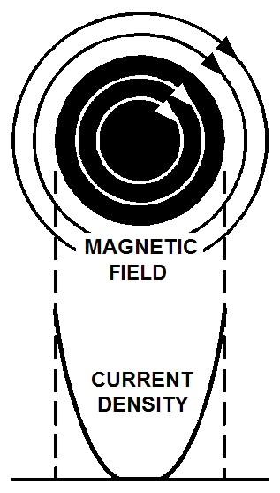
Figure 8-1: Current distribution in round wire (black). No current at center.
In conductors that do not have a round cross section, skin effect is even worse. Round conductors are the least affected by skin effect. Notice Figure 8-2.
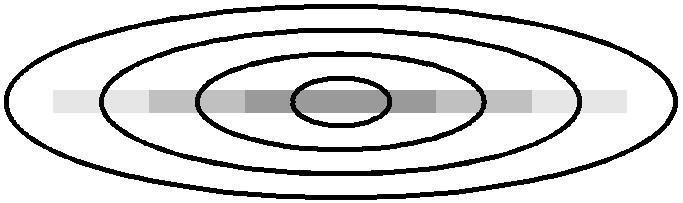
Figure 8-2: RF current and magnetic field in flat conductor. Current mostly at ends.
What significance does this have? Simply this: round conductors are best for RF. It is counterproductive to make the coupling loops of a cavity from flat metal strap. Commercial manufacturers often do use strap loops. This is only because they are mechanically easier to make for high current cavities. I prefer round conductor loops. Similarly, square cavities are less efficient than cylindrical cavities. The effect is not great, however, and successful duplexers can be made by soldering flat sheets together.
Another case in point, not related to duplexers, where flat metal straps are definitely not a good idea, is for compact transmitting loop antennas, sometimes called magnetic loops. These perform better made from round tubing, precisely for the same reason.
How bad is skin effect:
Skin effect is definitely a major problem in duplexers. It is significant at VHF and higher at UHF frequencies. Above that it becomes extreme. Let's look at some real numbers. The complete equation for calculating skin effect resistance is complex, but it may be simplified to:
To avoid calculation, Table 8-1 is this equation solved for RF frequencies 1 MHz through 1 GHz.
| Frequency | Skin Depth |
|---|---|
| 1 MHz | 0.0026 in. |
| 3 MHz | 0.0015 in. |
| 10 MHz | 0.00082 in. |
| 30 MHz | 0.00047 in. |
| 100 MHz | 0.00026 in. |
| 300 MHz | 0.00015 in. |
| 1 GHz | 0.000082 in. |
Table 8-1: One skin depth vs. frequency
We consider a skin depth to be the depth at which the current has decreased to 36.8%. Obviously some current is still flowing at one skin depth, but it will again decrease by another 36.8% for every additional skin depth. In practice we consider the current below three skin depths insignificant. Quite close to the surface is where most off the current is flowing.
At 450 MHz, skin depth is 0.00012 inches. Therefore, the effective thickness of the conducting surface is only .00036 in. Copper and aluminum may be good conductors, but for a conductor this thin there is now appreciable resistance. Multiply these figures roughly by three at 2M
Surface Treatment:
A common way to reduce skin effect losses is to electroplate the inside of the cavity with a more conductive metal. Since most of the current flows on the surface this technique can be effective, but generally only at or above UHF frequencies.
Silver, and sometime copper are the only practical choices for plating, and neither is possible on aluminum. Surprisingly, gold is not a worthwhile option here. As we saw earlier, gold is only used on connectors for corrosion resistance not conductivity. Copper is a better conductor than gold, and silver is only marginally better than copper.
For ham use, the cost and the marginal benefit of silver plating is impractical. Below roughly 1 GHz the thickness of the plate required is too great. At 450 MHz and below, especially for home construction, bare copper is perfectly adequate.
However, at lower frequencies there is one case, where electroplating can be effective. That is copper on steel. Unlike silver, as a plating material, copper is relatively inexpensive even if heavy plating is required. Several commercial manufacturers make excellent cavities out of copper-plated steel. Steel is otherwise totally unacceptable as we saw due to poor conductivity. I have personally not attempted copper plating at home, though I suspect it could be successfully done by some home builders.
Corrosion of Copper and Aluminum:
What about the corrosion that forms on copper or aluminum? Won't that reduce the effectiveness of a cavity? I had the same question when I first started making cavities. So I did an experiment. I took one of my copper UHF cavities, and measured its performance while it was still very dirty. I hadn't cleaned it up after assembly. It was black with copper patina.
Then I polished its inner surface to a mirror shine. I was dumbfounded to discover that the cavity's performance remained the same. Apparently the patina, as it is called, that collects on the surface of copper is not a problem in cavities, most likely because it is very thin and is also a conductor. Skin effect works for us here. As a result, and since that time, I only give my cavities modest cleaning merely for aesthetic reasons.
Aluminum is more or less the same, though the nature of the surface corrosion on aluminum is quite different. Copper patina is conductive, aluminum corrosion is an insulator. It is aluminum oxide, the very same substance rubies and sapphires are made of. Aluminum corrosion also has no noticeable effect on the RF currents running on the inside surfaces of a cavity.
Cavity Impedance:
The second major loss issue in duplexer filters is induced by the characteristic impedance of the cavity itself. Remember, a quarter wavelength coaxial cavity is just a section of large-diameter open-air transmission line. Like any transmission line it has a characteristic impedance. For air-insulated circular coaxial transmission line, the characteristic impedance is determined simply by the inner to outer conductor diameter ratio.
An early question for me was, does the characteristic impedance of a cavity have anything to do with its performance in a duplexer? That is, is the inner to outer diameter ratio important? And the answer is yes, quite a lot. I was surprised to find out that there actually is a "magic" characteristic impedance for a cavity. Figure 8-3, though surprisingly it isn't 50 Ohms, but 77 Ohms. At the specific inner-to-outer ratio for 77 Ohms, cavity loss is lowest.

Figure 8-3: Inner to outer conductor diameter ratio vs. relative loss
Notice that insertion loss is lowest when the inside of the outer conductor is 3.6 times as large as outside of the inner conductor. Again this translates to a characteristic impedance of roughly 77 Ohms.
Table 8-2 is the 3.6 to 1 ratio calculated for commercial aluminum cake pans with the copper pipe size to use for the center conductor. As you can see from the graph, small variations do not introduce significantly greater losses. Also, the price of copper pipe takes a sharp jump above 2 in. I stick to 10 in. or smaller cake pans, even for 6M or 10M cavities. For example, the inner conductor of our sample cavity is 1 1/4 in. copper pipe. This is a little small, but is close enough. If you intend to build an actual duplexer from this design, 2 in. pipe will yield slightly better insertion loss.
| Pan Size | Center Conductor | Copper Pipe |
|---|---|---|
| 12 in. | 3.3 in. | 3.0 in. |
| 10 in. | 2.8 in. | 2.5 in. |
| 9 in. | 2.5 in. | 2.5 in. |
| 8 in | 2.2 in. | 2.0 in. |
| 7 in. | 1.9 in. | 1.5 in. |
Table 8-2: Cake pan vs. center conductor pipe size
As a sidelight, the graph also illustrates why 75 Ohm coax is normally used for receiving purposes, such as TV cable. At this characteristic impedance, coax has the lowest losses? Why then, you may ask, do we use 50 Ohm coax for transmitters? Shouldn't they also use the lowest loss coax? Yes, they should if one only considers loss. 75 Ohm coax can't handle nearly as much power as 50 Ohm coax. The best power handling capacity in coaxial line is achieved at roughly a 30 Ohm characteristic impedance. 30 Ohm cable is difficult to manufacture, so 50 Ohm cable has become the accepted compromise for coax carrying RF power. In a cavity, however, losses are extremely important. So we want to use the optimum impedance of 77 Ohms, again an outer-to-inner diameter ratio of 3.6 to 1.
When I learned about this magic ratio, I wondered, "Doesn't that create a mismatch between the 50 Ohm coax and the cavity?" Yes it does, but it does not matter. I'll have more to say on this later when we talk about lines, but for the moment, let me state another basic cavity principle. Any mismatch that takes place at the input of a cavity is reversed at the output, provided both loops are equally configured.
Bandwidth Verses Insertion Loss:
Next we come to the most important duplexer concept of all, bandwidth vs. insertion loss. If everything were perfect, a duplexer would pass only the frequencies we wanted and totally reject all others. What's more, there would be no insertion. In other words the bandwidth would be extremely narrow and the insertion loss would be zero. As we know, this does not happen in practice.
It is, though, possible to have reasonably narrow bandwidth. Bandwidth is directly proportional to the Q of the cavity. The Q is determined mostly by skin effect losses. If we assume that we have the ideal conductor diameter ratio of 3.6 to 1, a reasonable approximation for the Q of a copper cavity without any load is,
From this we can determine the bandwidth by,
Table 8-3 lists value calculated from these equations vs. outer conductor diameter, at 450 MHz.
| Diameter | Q (unloaded) | Bandwidth |
|---|---|---|
| 1 in. | 2300 | 195 KHz |
| 2 in. | 4500 | 98 KHz |
| 3 in. | 6800 | 65 KHz |
| 4 in. | 9100 | 49 KHz |
| 5 in. | 11300 | 39 KHz |
| 6 in. | 13600 | 33 KHz |
Table 8-3: Q vs. bandwidth for 450 MHz copper cavities with a 3.6:1 ratio
Notice the bandwidth figures. You may be surprised that they are so narrow. If you've had practical experience with duplexers, you probably were expecting bandwidths of Megahertz not Kilohertz, and you'd be right.
The reason for the difference is quite simple. The values are for unloaded cavities. In use, duplexer cavities exhibit far poorer bandwidth because they are loaded by the external equipment connected to them. In a real duplexer, there is a 50 Ohm load on both the input and the output. One is the 50 Ohm load of the antenna at the tee junction. At the other ports, the duplexer sees the 50 Ohm load of either the receiver or the transmitter. Each individual cavity also sees the same loads, since in a well designed duplexer the cavities are more or less transparent, as we learned above.
Therefore, every cavity is doubly loaded by 50 Ohm loads. What this does is to establish a new effective working Q for each cavity called the loaded Q. It is far, far less than the unloaded Q given in Table 8-3. That's why the working bandwidth of duplexer cavities is much greater.
The Effect of Coupling:
Before we can get an idea of how much the external loads reduce the unloaded Q of the cavity, however, we must look at another process that happens inside a cavity, that is, coupling. The 50 Ohm load impedance created by an external device is fixed, but the amount it actually loads the cavities is not.
The amount of loading depends on the arrangement of the loops in the cavities. You will recall from an earlier chapter that the size and orientation of a loop determines how much it couples to the cavity. If a loop is made large enough and correctly positioned, it will place the entire external load on the cavity. If, however, it is made smaller than this, or is rotated away from being perpendicular to the field, it will not place the entire external load on the cavity.
This leads us to a most important cavity concepts: the tighter the coupling, the wider the bandwidth. Notice Figure 8-4.

Figure 8-4: Bandwidth and insertion loss vs. coupling for over-coupled, critically coupled, and under-coupled.
Well if that's true, you may be thinking, then let's never use tight coupling, and the rejection in our duplexer of unwanted signals will always be good. That's a valid idea, except for one thing - and it leads us to another important principle: the less the coupling the more the insertion loss. Notice Figure 8-4. Here I show the same cavity with the loops progressively adjusted for loose (under) coupling, optimum (critical) coupling and tight (over) coupling. Notice that bandwidth decreases as the insertion loss increases. We can't have both - it's simple physics.
If we did not care how much insertion loss our duplexer has than under coupled cavities would provide all the Q we would ever need for good isolation between receiver and transmitter and protection against the neighbors. But if we don't want to lose receiver sensitivity and transmitter power, we need to use critical coupling and the largest cavities we can afford. In review, remember this. The loaded Q of a large critically-coupled cavity can be the same as that of a small under-coupled cavity, but the insertion loss will be less.
A Basic Compromise:
It should be obvious then, that the correct balance between bandwidth and insertion loss needs to be established in every duplexer. If we try to achieve for too little insertion loss, bandwidth and isolation will suffer. Anything tighter than critical coupling is counterproductive. The small improvement in insertion loss is not worth the price of the increase in bandwidth.
Therefore, when one is building a duplex for general-purpose applications, you should set the loops for critical coupling. Most commercial duplexers are this way. I also begin with In my home-brew designs I make the loops a little larger than necessary to achieve critical coupling when they are perpendicular to the magnetic field. Then all I need do is to rotate them slightly to achieve critical coupling. As we learned earlier, rotating the loops does not degrade the basic performance of a cavity, it merely reduces the amount of coupling.
What is a "Reasonable" Insertion Loss:
A very significant point here is to ask how much loss should we expect to have at critical coupling? This is where the uninformed duplexer may hear misinformation. Hams often strive for too little insertion loss. By now you should realize that learned, insertion loss is determined almost entirely by skin effect, which is a function of cavity diameter and cavity construction material. The informed user realizes that insertion loss is a fact of life. It is unrealistic to expect otherwise. Table 8-4 gives my personal rough guidelines, based on experience, for aluminum cavities for 2M. For copper cavities at 450 MHz, divide the diameters by three and the insertion loss by the conductivity difference between aluminum and copper of 1.5.
| Diameter | Insertion loss |
|---|---|
| 3 in. | 2.2 dB |
| 6 in. | 1.1 dB |
| 9 in. | 0.75 dB |
| 12 in. | 0.6 dB |
Table 8-4: Insertion loss for 2M aluminum cavities
The figures I have given are for loaded cavities installed in a completed duplexer. Therefore, a small amount of the loss included here is due to other factors. With care you may be able to achieve slightly better results.
The Next Step:
Now that we have a starting point, critical coupling, we are going to take another step that most duplexer users will complain loudly if told to do so. We are going to increase the amount of insertion loss, to knowledgeable decrease the bandwidth of our duplexer. The object is to achieve the best balance between economy and loss. For as we've seen, an oversized, overpriced critically-coupled duplexer will always work, but it is often not the best economy. This of course will evoke an attitude problem for some repeater owners. They do not like ANY increase in insertion loss, even if it will bring benefits.
Let's begin on the transmitter side. Again hams probably won't like this, but the two-way industry is generally willing to accept a 3dB loss of transmitter power to achieve the correct bandwidth. Yes, that's giving up half of the transmitter's power in the duplexer. Admittedly, that's not what we'd like, but it truly is an acceptable compromise. Amateurs want "absolutely every microwatt" of power they can get. Commercial operators usually know better.
So unless you have all the money in the world and have all the space you need in a repeater cabinet, transmitter insertion loss of 3dB is acceptable in practical repeater installations. Often we can do better, but don't feel "put upon" if you can't.
The reason this is so is because losing half the power in a worse case situation is really not that bad. Especially at UHF, but even at VHF, the service area of a repeater with only half the power is actually very little different than it would be at greater power. Terrain is a far bigger factor than power. That's why most commercial repeaters are less than a hundred watts. Modest power is really quite adequate. A kilowatt isn't necessary. So neither is there any need to cry over losing half of your power in a duplexer if it will net significant gains in economy with performance. A couple extra watts isn't worth the price.
The same is true for the receiver side of a duplexer, except that acceptable insertion loss can surprisingly sometimes by much greater. Again we would like as little loss as possible, but once again it is not always that important. I've seen several cases where intentionally increasing the insertion losses on the receive side beyond of 3dB has improved the repeater's actual performance quite noticeably. It's ALWAYS an option worth investigating.
As we saw in an earlier chapter, the average level of band noise at your repeater site is the biggest determining factor of how much sensitivity you can practically use. For example, in chapter 1, we saw that if the average noise level at your location is -110 dBm, then all you need is an overall receive sensitivity of roughly 0.71 microvolts. But if your receiver has a natural sensitivity of 0.22 microvolts, like our sample receiver, simple math says that you can afford to take a big 10 dB loss in insertion loss on the receive side of your duplexer without any loss in system performance whatsoever. Again, don't get upset at having to give up 3dB on the receive side of your duplexer to achieve good filter action.
Never forget that if you intentionally reduce overall system sensitivity by admitting greater insertion loss on the receive side, you will always instantly improve system bandwidth. So don't strive for the last microvolt of gain and the absolute minimum of insertion loss in a duplexer. It is not always the best choice. You will gain much more by using only enough gain and as much insertion loss to let your receiver hear efficiently, and no more.
I can recall the first repeater site on which I saw this principle applied. I had adjusted my home-brew duplexer for the absolute minimum insertion loss on the bench. When I put it on the hilltop it worked okay, but I was experiencing a little interference from a nearby paging transmitter. So reluctantly, I twisted the loops in the receive band-pass cavities for an increase of insertion loss to eliminate the paging transmitter. The interference immediately went away, and to my great surprise the repeater could now actually hear weaker signals. Case in point.
Increasing receive-side insertion loss in a duplexer in order to narrow the bandwidth is always a compromise worth considering. It is much like adding another cavity. And if you are using a preamp or an outboard power amplifier, it can be worth its weight in RF gold. Duplexer insertion loss is NOT always your enemy.
Contact Information:
The author can be contacted at: jportune [ at ] aol [ dot ] com.
Back to the top of the page
Back to Book Index page
Back to Antenna Index page
Back to Home
This article created on Wednesday 09-Jan-2019.
Article text, images and photographs © Copyright 2019 by John Portune W6NBC.
Layout and conversion to HTML © Copyright 2019 by Robert W. Meister WA1MIK.
This web page, this web site, the information presented in and on its pages and in these modifications and conversions is © Copyrighted 1995 and (date of last update) by Kevin Custer W3KKC and multiple originating authors. All Rights Reserved, including that of paper and web publication elsewhere.