Antenna Index page
Home page
Duplexer Tuning
By John Portune W6NBC

|
Book Index page Antenna Index page Home page |
Cavity Duplexers Chapter 6 Duplexer Tuning By John Portune W6NBC |
|
We'll now assume that you have built a complete duplexer or that you have a commercial unit to tune. How do you do it correctly? It's quite easy, even in the field. Again, a spectrum analyzer with a tracking signal generator makes things easier, but you can definitely also do it with the basic setup. [Ed: A return loss bridge also makes Bp tuning a breeze.]
First, review the basic architecture of a duplexer, Figure 6-1. It is essential to keep it in mind as you are tuning. I've seen many an ignorant novice badly misadjust a duplexer by not paying careful attention to this basic structure.
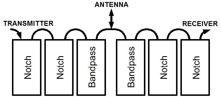
Figure 6-1: Layout of the average duplexer
Again, there are two sides, receive and transmit. Both typically have two notch cavities and a single bandpass cavity, configured as shown. The Bp cavities are adjacent to the antenna input. Despite the disposition of the cavities, the tune-up procedure will be similar.
Tune-up Procedure:
Table 6-1 lists the basic rules for tuning a duplexer. Notice that there are four combinations. One pair applies to the transmit side, the other to the receive side. At a casual glance both may seem the same. Look closer. The frequencies are reversed. Hence there are four rules, one for transmit Bp, one for transmit Br, one for receive Bp and one for receive Br. Note the distinct differences and the pattern. Memorize these rules; they are absolutely basic and essential.
| TX Bp | Max. at the transmit freq. |
| TX Br | Min. at the receive freq. |
| RX Bp | Max. at the receive freq. |
| RX Br | Min. at the transmit freq. |
Table 6-1: Tune-up rules
For the actual tune-up procedure, there's an overall rule that I consider mandatory - tune each cavity separately, first. Completely disconnect one cavity at a time from the duplexer by removing its normal inter-cavity cables. Then tune it on its own. The need for individual cavity tuning is this: a mistuned cavity down the line can very easily induce incorrect tuning in the one you're working on. What's more, individual cavity tuning will almost always get you very close to an ideal over-all tune up. You'll rarely need to readjust cavities assembled as a complete duplexer.
When tuning a duplexer, it is not necessary to make graphs as we did during the design phase of the cavities. All you are doing now is adjusting for either a peak or a dip. Here an MFJ-259, or similar, is easier to use than the simple transceiver method. With it you'll find the Br notch at maximum SWR, the Bp peak at minimum SWR. Notice that this is the reverse of power.
Tuning is also a little easier, if you realize something else. Duplexer cavities are symmetrical. In other words, they have no specific input or output. The two inputs are the same and can generally be reversed. You may therefore connect the Wattmeter and a 50 Ohm load to either connector, and your transceiver or MFJ-259 to the other.
FIRST, as Table 6-1 shows. tune the bandpass cavities for maximum through-put power (or minimum SWR). Remember, always tune Bp first, it's always vital. Also don't forget to select the correct frequency when you move from one side of the duplexer to the other, again according to Table 6-1.
Then, only after you have tuned all the Bp cavities, tune the notch cavities on BOTH sides. Again, as Table 6-1 shows, tune the notch cavities for minimum power (or maximum SWR). Once again remember to change frequency as you change sides. Notch cavities are more critical to tune. You could use a receiver with an S meter for a finer adjustment. If so, place a 50 Ohm pad (20 dB or more) in front of the receiver to prevent damage to its front end. The pad also insures that the receiver presents a 50 Ohm load to the duplexer. Without proper loads you WILL always misadjust.
Finally, after tuning all the cavities individually, reconnect the entire duplexer. Now you may, if you still feel it is necessary, perform a fine adjustment of the whole unit. DO NOT go straight to this without first tuning the cavities individually. The importance of this can not be overemphasized.
For an overall fine tune, connect the Wattmeter and dummy load to either the transmit or the receive port of the duplexer. Also terminate the other port with a 50 Ohm load. This is very important. Then connect your transceiver (or MFJ-259) to the antenna port. Again following Table 6-1, first touch up the Bp cavity(s) on both sides. Finally, touch up the Br cavity(s). Never "tweak" just the notch cavities without going through the full procedure. Experience has shown me that notch cavity adjustment in a fully connected duplexer can be the pathway to disaster, especially for the newcomer.
For the Home Builder:
In the following chapters we'll now complete the picture, especially for those who want to roll their own or modify a commercial unit for ham-band use. We'll dive into loops a little deeper and then into lines and losses. Even for those who do not choose to build their own, these final chapters involve important comprehension principles.
Contact Information:
The author can be contacted at: jportune [ at ] aol [ dot ] com.
Back to the top of the page
Back to Book Index page
Back to Antenna Index page
Back to Home
This article created on Wednesday 09-Jan-2019.
Article text, images and photographs © Copyright 2019 by John Portune W6NBC.
Layout and conversion to HTML © Copyright 2019 by Robert W. Meister WA1MIK.
This web page, this web site, the information presented in and on its pages and in these modifications and conversions is © Copyrighted 1995 and (date of last update) by Kevin Custer W3KKC and multiple originating authors. All Rights Reserved, including that of paper and web publication elsewhere.