Antenna Index page
Home page
Performance
By John Portune W6NBC

|
Book Index page Antenna Index page Home page |
Cavity Duplexers Chapter 5 Performance By John Portune W6NBC |
|
In this chapter well wade knee-deep into a sea of old wives tales often heard in the repeater world. Much misinformation commonly exists in knowing what to expect from a repeater's duplexer. There are useful compromises here that we can intentionally make that will benefit us? For all these performance factors must be coordinated if top repeater performance is to be achieved.
To begin to get at this vital area of knowledge, let's begin with the two most-common terms used to describe how well a duplexer must perform, that is how much loss it will introduce: (1) isolation and (2) insertion loss. Then, later in this chapter we'll also look at how well the (3) receiver and the (4) transmitter must perform. These are the biggest area of old wives tales in the repeater world.
Isolation:
Ideally, in the "perfect" duplexer, the transmitter of the duplexer should be "invisible" to the receiver on the opposite port, and vice versa. In practice, however, this is never totally true. Actually the cavities on both sides of a duplexer only ever "reduce" the unwanted signals, just sufficiently for the repeater to function. Determining how much this reduction needs to be is the key issue in knowledgably managing a repeater and its duplexer. We call this the isolation of the duplexer. It is generally stated in dB, the relative ratio of signal weakening. And again, it is never perfect.
Recall from Table 1-1, Chapter 1 that our sample receiver can hear a tiny 0.22 microvolt signal on an antenna also carrying a transmitter signal 150 dB (a thousand million, million times) stronger. But does the duplexer have to provide all these150 dB of isolation? Actually it doesn't, and this is an important repeater concept. The reason it doesn't is simple; the repeater's receiver provides some of the dB, all by itself. That's because its "front end" is frequency selective. This partially rejects signals not on center frequency. That's the meaning of selectivity. The cavities of the duplexer, therefore, only have to provide part of the total required 150 dB of isolation between receiver and transmitter.
This is also of course why a repeater has a frequency "split" or "offset." The input and output frequencies are intentionally placed apart. For example, on the 440 MHz band, the split is commonly 5 MHz and on 2M, 600 KHz. It's different for each band by convention, but the main function of a repeater's offset is to provide a large part the isolation needed in a repeater between receiver and transmitter.
Insertion Loss:
The second main important performance characteristic of a duplexer is insertion loss. It's the amount of power or sensitivity that we give up for the duplexer to function. There is always some, again normally stated in dB. For example, if the output of our 100 Watt sample transmitter becomes 50 Watts after passing through the duplexer cavities, the transmit insertion loss is 3 dB (half power) . The same applies to the other side of the duplexer. Insertion loss is specified for both sides and is usually a different value for each.
Jumping ahead briefly, insertion loss is mostly caused by RF skin-effect resistance loss on the inner surfaces of the cavities. It is also affected by cavity diameter and the coupling factor of the loops. For now, merely recognize one basic fact about insertion loss. It is NOT always bad.
Insertion loss is the one performance characteristic of a duplexer that is most open to knowledgeable compromise, even if most repeater owners consider it their deadly enemy. For one can often derive increased repeater performance by intentionally increasing the insertion losses in the duplexer. I have often seen a repeater become better able to hear weak signals by doing just that. We'll give major attention to this later.
No Duplexer is Perfect:
We of course would like to always have a "perfect" duplexer. Let's suppose that we could actually buy such a device - one with infinite isolation and zero insertion loss. Our "fantasy" duplexer would be a universal "fits-all," wouldn't it? It would behave flawlessly on any "RF dirty" hilltop, no matter how much power our repeater is outputting and how sensitive and selective our receiver is.
Coming down the scale just a bit, how well will a high-cost "top-of-the-line" duplexer perform in the same situation? It would have perhaps 120 dB of isolation and as little as one dB of insertion loss on both sides. Again, wouldn't such a duplexer work well in NEARLY all situations?
Now, consider the other end of the spectrum, a small low-priced mobile duplexer with only 40 dB of isolation and as much as 3 dB of insertion loss. Can we use it? Actually, we can. Recognize here, though, that such a duplexer would not function well in nearly as many situations as the perfect duplexer or even the top-of-the-line model.
For example, a low-end duplexer might be okay for a small repeater at a quiet home QTH with a slightly "numb" receiver. But it certainly wouldn't be satisfactory for a sensitive high-power repeater on a dirty RF hilltop. Also a repeater with a low-end duplexer might fail, had it been okay before, if its owner increases the transmitter's power output power or installs a receiver pre-amp. A high-end duplexer, on the other hand, would likely tolerate such additions.
The vital point here to realize is, the better the duplexer the more places one can use it without understanding it. This might seem to suggest that you should always use a top-of-the-line commercial duplexer. Not really. High-end duplexers are expensive. Can you always afford the price? Wouldn't it be better to exchange knowledge for cost? Well, there's good news. Let's now see some well-informed compromises we can make. You may net big savings here without any significant compromises in performance.
FACTOR ONE: Band Noise:
The biggest factor in knowing how good (or expensive) a duplexer needs be is band noise on your hilltop. The radio spectrum is full of noise. Notice Figure 5-1. Most repeater owners pay little attention to the average band noise at their site, often to their detriment. On the other hand, hams who work the HF bands, know well how important band noise is. On a noise-free day one can often "work the world." On a noisy day, a numb receiver is as good as an expensive one. To the repeater owner, noise is just as important. Working with it knowledgably is vital to maximum repeater performance.
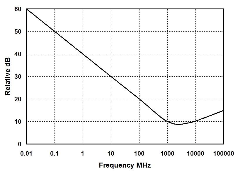
Figure 5-1: Generalized noise across the radio spectrum
RF noise comes from a variety of sources. The sun, the earth's atmosphere and even our galaxy all make radio noise. We call this natural kind of noise QRN. Industrial machinery, power lines and other transmitters create man-made noise or QRM. Together all these sources create a background of noise at your site. It is very real and always there.
Most repeater owners pay little attention to it, however. Yet in deciding how good (how expensive) a duplexer needs to be, and how sensitive to make your receiver, the average noise level at your site is vitally important. Here now are the important basics.
As you can see from Figure 5-1, on average, noise in the radio spectrum is much higher for low frequencies than for high. In fact, total band noise decreases roughly in inverse proportion, all the way from VLF into UHF. As a simple "rule of thumb" for noise on the radio spectrum, when the frequency doubles, the noise drops to half (down by 6 voltage dB). Slightly above 1 GHz spectrum the noise finally reaches a minimum and then begins to rise again. New noise sources become dominant, such as atmospheric ions. We needn't, however, concern ourselves in this book with frequencies above a Gigahertz.
So what is the big concern about RF noise to the repeater owner? Simply this. Both the RF noise spectrum noise and the noise in our own receiver, set a very hard limit on how sensitive our receiver ever needs to be and how well a repeater can perform. I used to hear ill-informed repeater owners say that their repeater can hear a 0.1 microvolt signal. Well perhaps that is true when the signal is coming from a quiet signal generator. But if the noise floor at their repeater site never drops below say one microvolt, such a receiver is of no use.
Consequently, if you will knowledgeably match your repeater's overall system sensitivity to the hilltop, you may well find that you do not need as much duplexer as you think or a receiver with "killer" sensitivity. It is a simple fact of repeater life, that a receiver can't hear signals lost in noise. If noise is high, all the receiver sensitivity in the world is fundamentally worthless.
If you don't believe this, just try telling an HF ham trying to work 40 M who can't hear anything because of a 10 over 9 noise level that he needs to raise the sensitivity of his receiver. He knows that all that will do is bring in more noise. Noise truly does set a very hard limit on how sensitive a repeater can practically be, and therefore how much insertion loss a duplexer can have and still function at peak performance at that site. I have several times seen that be intentionally increasing the insertion loss in a duplexer, to narrow the overall system bandwidth, enables a repeater to hear weaker signals in the noise.
For other bands, use the simple 6 dB per octave rule of thumb. That is, you can expect the noise to be on average 5 dB (three times) higher on 2M, or -111 dBm. This places the typical total noise on the average radio hill at roughly 1 microvolt. A receiver much more sensitive than is largely unnecessary, most of the time. If the noise drops below average, or if the user takes steps to reduce the noise figure of the overall system, a more sensitivity receiver helps. These are of course "average" figures.
In actual practice, the noise on real hilltops does routinely rise and fall above and below the average figure for that site. Haven't you ever noticed that there are days when you can't get into your favorite repeater as easily from a particular location? This is most likely due to higher noise on that day. I have for example, seen the noise as high as -90 dBm (7.1 microvolts) at 450 MHz on an actual hilltop. At such a time A VERY "numb" receiver or a duplexer with a lot of insertion loss is perfectly okay. On a quiet day, it wouldn't be.
Impact of Noise on the Duplexer:
Many repeater builders wonder why commercial manufacturers don't make their receivers more sensitive. Is it because they don't know how, or can't? Hardly. It is because they are aware of the noise floor. They have already likely given the receiver you are putting in your repeater as good a "front end" as it can reasonably use. In many cases, in fact, it may be more sensitive than you actually need. It is probably difficult for most hams to realize that a receiver can be "too" sensitive. Just recall, your duplexer has to match every dB of sensitivity your receiver has. Again, becoming knowledgeable of the average noise level at your repeater site is vital.
Measuring the Noise:
Fortunately there is a relatively easy way to make a satisfactory estimate of the noise at your repeater site: Just use your repeater's receiver, a calibrated FM signal generator and your repeater's normal antenna. You will also need two low-power 50 Ohm dummy loads or terminators and a hybrid combiner.
What a hybrid combiner? It is a passive mixing device that let's you feed both your antenna (through the duplexer) and a calibrated signal generator into your receiver at the same time. The combiner keeps either signal from affecting the other. A hybrid combiner is required for a proper estimate of total noise.
It is quite easy to build one as a coaxial hybrid ring combiner. See Figure 5-2. Make it from 50 Ohm coaxial cable and BNC "T" connectors. The quarter wavelength (in coax) phase relationships between the ports create the needed isolation between the two signals. This kind of combiner is good only for one band, however. It is a "tuned" device. You can, however, make alternate cable sets for the same "T" connectors.
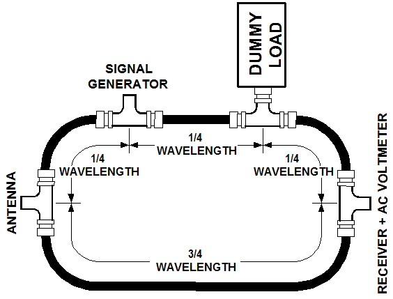
Figure 5-2: Ring hybrid combiner made from coax
Don't forget that the coax section must account for velocity factor. On 2M, open air quarter wavelength is roughly 20 in. You need, therefore, to make the distance from the center of one BNC "T" to the next connector, 20 in. multiplied by the velocity factor of the coaxial cable - typically 0.6. Look up the velocity factor for the cable you are using in a radio handbook. For a velocity factor of 0.6, the center-to-center distance on the right would be 12 in. for a 1/4 wavelength cable and 36 in. for a 3/4 wavelength cable.
The Measurement Procedure:
The noise level, and the output of the signal generator, are now roughly equal. Read this level from the signal generator. We call it the minimum discernible signal (MDS) your receiver can usefully detect. It incidentally also includes the noise made by your receiver. By repeating this measurement on a number of subsequent trips to your hilltop, you can factor out your receiver's own noise and gather a perfectly reasonable estimate of total external hilltop noise. And from this you can determine the required receiver sensitivity for your site as well as begin to know how much duplexer you need. You may be surprised; I was.
FACTOR TWO: Receiver Sensitivity and Selectivity:
By now it should also be evident that we need to know our receiver's performance if we ever expect to knowledgably match it to the duplexer and the hilltop. Two factors matter here: (1) sensitivity and (2) selectivity. The second, often totally overlooked by repeater builders, is most often much more important than the first.
Sensitivity is easy to measure. Radio technicians often do so when they visit a site. Merely connect a calibrated signal generator to the receiver and adjust the generator's output level until the receiver just barely can't hear the signal. This is the receiver's sensitivity.
Lets use a 440 MHz repeater as an example. Again we'll assume a receiver sensitivity of 0.22 microvolts or minus 120 dBm. Without any additional gain, this sensitivity is a naturally a good match to the average noise level at a typical UHF repeater site, that is -110 dBm. Remember, we want only a little more sensitivity than it takes to get down to the noise. An extra 10 dB is a realistic amount of headroom. Now let's measure our receiver's selectivity, the other vital factor we need to correctly match our receiver to its environment. Remember, a receiver with the same sensitivity as another, but with poorer selectivity may work poorly in a repeater where the other will perform flawlessly.
Selectivity Measuring Procedure:
Plot the results on a graph. It should look similar to Figure 5-3, a graph I compiled from an actual 440 MHz receiver. As you can see, at the center frequency, a very tiny signal (-116 dBm) will desense the receiver. But the more you move away from the center frequency the stronger the off-channel signal has to be to cause receiver desense. This is due to the receiver's selectivity.

Figure 5-3: 440 MHz Receiver desense profile
This curve shows us that for our example receiver an off-channel signal five MHz lower in frequency must be 88 dB stronger to cause desense than an on-channel signal of -116 dBm. So at the normal 5 MHz frequency spilt of a 440 MHz repeater, the receiver's selectivity already provides 88 dB of the total 150 dB isolation needed in our example. The duplexer, therefore, only has to provide 62 dB of isolation. That's a lot less than we pay for in a top-of-the-line duplexer.
We do though actually need a bit more than 62 dB for a couple of reasons. Something more like 90 dB is in order. Much of this, as we'll saw earlier, is because duplexer cavities drift with temperature. So we add some additional dB of isolation to compensate for this. Also, transmitters are never perfect. They don't put ALL their energy on only the output frequency. We often call a transmitter's off channel energy "dirt." Hence the dirt from our own transmitter causes additional desense. Outboard transmit power amplifiers are often notoriously "dirty." Adding one will frequently demand a better duplexer.
Preamps:
While we are on the subject of sensitivity, let's pause briefly to consider preamplifiers. In recent years preamps have become the shining star of the ham repeater world. At least a lot of hams look at them that way. Unfortunately, they can cause problems in respect to selectivity, hence how much duplexer is needed.
The reason is, after-market preamps are broadband devices. They have little or no selectivity. They amplify the noise, the dirt and the grunge just as much as they do the signals we want. Yes, of course, they do add sensitivity and can also improve the noise figure of our receive system. But quite often they do this at the expense of an undesirable increase in total receive bandwidth. As we have painfully seen, reducing receive selective is deadly in a repeater. It instantly places an increased burden on the duplexer, which may now no longer be able to properly our isolate receiver and transmitter particularly if they are low-end models. So don't be surprised if a preamp increases the "grunge."
A possible benefit of using an after-market preamp, as I just mentioned, is an improvement in the overall receive system noise figure. Some high-end preamps employ higher-quality and lower-noise front-end devices than some older or ham-grade receivers. So if the repeater owner is also willing to add some additional outboard bandpass cavities. to help control the increased receive system bandwidth, a preamp can add useful overall noise figure reduction. This is often much more helpful than simply increasing the gain.
So before installing a preamp, in hopes of creating a "killer" repeater, spend the time to measure the sensitivity and selectivity of your receiver as well as the working noise level at your site. You may be in for a surprise. For if you already are slightly below the working noise floor, more gain from a preamp may not help.
I go by a simple rule of thumb with preamps. On really high mountaintops, where the desired signals are strong, and at remote sites that are difficult to get to, I avoid preamps. Most modern barefoot commercial receivers have sufficient sensitivity and noise figure for these situations. At lower altitude sites, such as at a home QTH, or where the site is easy to get to, a preamp may help. Never, though, look at preamps as a miracle cure.
Selecting a Receiver:
In light of what we have seen, you may now be able to guess that some receivers are not suitable for repeater service. In commercial repeaters, the manufacturer designs the receiver accordingly. Ham repeater can rarely do this. So let's briefly talk about how to select a receiver for repeater use.
Commercial crystal-controlled mobile two-way transceiver receivers, the type most amateur repeater builders have long used to build repeaters, are generally a good choice. That's because the more-recent models of crystal-controlled commercial transceivers are narrow-band devices. They have good front-end selectivity, often employing narrow-band helical resonators. They were designed to operate on only a few adjacent frequencies in commercial mobile service. So the manufacturer designed them with narrow-band filters directly in the front end. This kind of receiver works very well in a home-brew repeater. Unfortunately they are disappearing from the commercial two-way radio world. Instead, the receiver used in most ham transceivers, and newer fully synthesized commercial mobile transceivers, are built to cover a wide range of frequencies. This precludes narrow-band front ends and good front-end selectivity. Instead, selectivity is created by IF filters.
This method works okay in mobile service, but unfortunately the front end of such a receiver is wide open to off-channel interference when used in a repeater. Repeater builders should try to avoid this type. To state this as a simple rule of thumb, front-end receiver selectivity is much less expensive than having to add more cavities to a duplexer.
Fortunately at the time of the writing of this book, there are still many late-model crystal-controlled commercial mobile transceivers on the used commercial radio market. Thousands are still in regular service. Look for one when you are building a repeater. Avoid fully synthesized receivers, especially those made for ham mobile service. They are normally a poor choice. Again, isolation is much less expensive in the front end of a receiver than as a higher-end duplexer or more cavities.
The type of transmitter you select for repeater use is also important. We got a clue of this above in mentioning the need for headroom in a duplexer. Two transmitter characteristics are important (1) power and (2) purity.
Transmitter Power:
It is a simple law of physics, but the amount of duplexer you need is directly related to the power of your transmitter. Take the time to look back at Table 1-1, Chapter 1. It will be evident that a 10 watt transmitter needs 10 dB less duplexer than a 100 watt transmitter. I'm amazed how many repeater owners do not grasp this.
For example they assume that their duplexer will still automatically work well after they have installed a power amplifier. More power ALWAYS theoretically requires more duplexer. A duplexer that is entirely sufficient for a 10 watt repeater may now badly desense if a 100 watt power amplifier is installed. We can't escape basic physics. Though if you have made the measurements above, you will know if you have the headroom to tolerate a power amplifier.
Transmitter Purity:
Transmitters, like receivers are not perfect devices. In Camelot, transmitters ONLY produce power on their center frequency. Unfortunately, in the real world, they don't. Considerable off-center-frequency energy always exists. Notice figure 5-4. It is a spectrum analyzer display of a portion of the FM broadcast radio spectrum containing several transmitters. Notice that each transmitter (the spikes) creates energy over a range of frequencies, not just on the carrier frequency.

Figure 5-4: Spectrum analyzer display of part of the FM radio broadcast band
Transmitter energy does not exist just on the carrier frequency. In other words, transmitters also have bandwidth. Further, by its very nature, modulating the carrier with audio, for example, creates sidebands - more off-carrier energy.
Returning briefly to the basic architecture of a duplexer for a moment, you should now be able to grasp why the transmit side of a duplexer must also have notch cavities. On the receive side. the reason for the notch cavities is simple. The receive-side notches suppress the transmitter's center frequency. But what do the transmit-side notches do? They suppress off-carrier transmitter energy which ends up on the receiver's center frequency. This explains why, as the little tuning chart in chapter three specifies, one tunes the transmit-side notches to the receive frequency, just the opposite of the receive-side notches.
As we said earlier, we affectionately call the energy that exists off of the transmitter's carrier frequency "dirt." Much to our dismay, some of it always is present on the center frequency of the receiver. Transmitters very a great deal in how much dirt they generate, but getting rid of transmitter dirt is the primary job of the notch filters on the transmit side of the duplexer.
So again we ask the question, how well must the transmit notch cavities work? It probably won't surprise you, but the answer is similar to the notches on the receive side. It depends on how strong the dirt is, and how selective and sensitive the receiver is. Sound familiar?
Let's expand this just a little for emphasis. Dirt is definitely weaker than the signal the transmitter is generating on its carrier frequency. But it is always still far too strong not to need to be notched out on the transmit side. Remember, the receiver is very sensitive. The dirt only has to be 0.22 microvolts for the receiver to hear it quite well. Again by using Table 1-1, Chapter One, we discover that 0.22 microvolts is a mere 0.000,000,000,000,001 Watts. The cleanest transmitter in the world makes a lot more dirt than this on the receiver's frequency, even with the repeater's frequency split. That's again why we need notch filters on the transmit side of the duplexer. They remove transmitter dirt.
Therefore, just like on the other side, we need to know the strength of the dirt before we can specify how much isolation we need from the transmit-side notches. To measure dirt, a spectrum analyzer IS required.
Transmitter Dirt Measurement Procedure:
Let's say its 85 dB weaker than the transmitter, with an absolute level of -35 dBm. Our duplexer, therefore, only need to have enough isolation in the notch filters on the transmit side to reduce the dirt to below the noise of -110 dBm in our example. This means that the filters on the transmit side of our duplexer would have to provide at least 75 dB of isolation. I've added another 10 dB for headroom. Even so, 85 dB is much less than provided by a top-of-the line duplexer.
As a final point on dirt, add-on power amplifiers normally generate more dirt than barefoot transmitters. Therefore, if you add a power amplifier to your repeater, be forewarned. You may need to add quite a bit of additional transmit-side notch cavity isolation.
A Simple Desense Test:
If you don't have access to a spectrum analyzer (most hams don't) there is a simple useful way to evaluate everything we have covered in this chapter. It is a simple test all repeater owners should perform on their repeater(s). It won't show you where the problems lie, if they do exist, but it will tell you if your transmitter is desensing your receiver.
In other words, if your repeater passes this test, it is working fine despite how much power you are running, how expensive your duplexer is, what kind of antenna your repeater has, if it has a receiver preamp or after-market power amplifier. This test also won't however tell you anything about the noise level at your site. But it is a good starting point.
If the duplexer is properly isolating the receiver from the transmitter, you will hear no desense in the weak input signal. If you do hear a change, you are experiencing desense. If you have installed either a preamp or an accessory power amplifier, try disabling it. If the desense goes away, you now have some indication of what the desense is being caused by. I never take a new repeater to a hilltop until it can pass this test.
In review, isolation, insertion loss, receiver and transmitter performance are all critical to knowledgeably work with. Mainly by not asking too much of any of these we arrive that the most efficient and economical configuration for a repeater. Many hams, and perhaps a few commercial operators, need to re-evaluate the many old-wives tales that exist in this arena.
Contact Information:
The author can be contacted at: jportune [ at ] aol [ dot ] com.
Back to the top of the page
Back to Book Index page
Back to Antenna Index page
Back to Home
This article created on Wednesday 09-Jan-2019.
Article text, images and photographs © Copyright 2019 by John Portune W6NBC.
Layout and conversion to HTML © Copyright 2019 by Robert W. Meister WA1MIK.
This web page, this web site, the information presented in and on its pages and in these modifications and conversions is © Copyrighted 1995 and (date of last update) by Kevin Custer W3KKC and multiple originating authors. All Rights Reserved, including that of paper and web publication elsewhere.