Antenna Index page
Home page
Temperature Drift
By John Portune W6NBC

|
Book Index page Antenna Index page Home page |
Cavity Duplexers Chapter 4 Temperature Drift By John Portune W6NBC |
|
This chapter is a side issue, but one of considerable importance. How does temperature affect a duplexer? With a commercially-built unit, a repeater owner does not need to pay much attention to this; it has been dealt with by the manufacturer. For the home builder, it is of major concern, however. The do-it-yourself builder must make provision during the design phase to keep home-brew cavities "on tune" as the weather changes.
We likely learned in grade school science class that most substances in the universe expand as they get warmer. The metal used in a cavity is no exception. Table 4-1 is the thermal expansion of common metals, expressed in percent per degree F.
| Metal | % / °F |
|---|---|
| Aluminum | 0.00131 |
| Cast Iron, gray | 0.00058 |
| Chromium | 0.00033 |
| Copper | 0.00098 |
| Invar | 0.00007 |
| Iron, pure | 0.00068 |
| Red Brass | 0.00104 |
| Carbon Steel | 0.00078 |
| Yellow Brass | 0.00113 |
Table 4-1: Thermal expansion of metals
Notice that copper expands or contracts 0.00098% for every degree F. Aluminum has a higher coefficient, 0.00131. How much then, you are probably asking, does this affect the tuning of a cavity? Let's take some real numbers and you'll see.
For a range of 100 degrees F - reasonably for a radio hilltop - the center frequency of a copper 2M cavity drifts 143 KHz. Our aluminum 2M cavity drifts 191 KHz. It would be 436 KHz for a copper 440 MHz cavity. These figures are obtained by multiplying the percentage of change of the length of the center conductor per degree, by the frequency and then by the total number of degrees. Thermal expansion is essentially linear over a wide range.
Now examine Figure 4-1. It is our sample cavity in both Bp and Br configuration. You'll easily see how significant temperature change is for the two. The bandwidth in Bp configuration is 3.6 MHz, for Br it is 200 KHz. Therefore, it is evident which configurations will experience difficulty with drift of 143 KHz, the Br notch cavity, the configuration that fulfills the main filtering responsibility in the duplexer.

Figure 4-1: Bp vs. Br bandwidth
If there were no temperature drift, uncompensated narrow-bandwidth notch cavities would always keep a repeater at full efficiency. But if the notch cavities drift down in frequency on a hot day, and no longer notch effectively, a noticeable loss of repeater performance will be experienced. Therefore, home-brew notch cavities clearly require temperature stabilization.
Stabilization Methods:
The preferred method for commercially-built cavities is to employ a rod made of a metal, called Invar, a nickel steel alloy that has a uniquely low coefficient of thermal expansion (7% that of copper). See Table 4-1. The length of the center conductor is controlled by the Invar rod. It changes length so little that the cavity stays within acceptable limits as the temperature changes. Expansion of the outer shell of the cavity, as we learned earlier, does not affect cavity tuning. Invar, however, is not a hardware-store material. Its use by the home builder is prohibitive. Also, sliding fingers to permit the center conductor to move up and down are required. They are well beyond home brew. So we will need to find another method. The one I prefer is simple, yet quite elegant. As a bit of trivia, it is based on a method devised over two centuries ago by famous British clock maker, John Harrison of sea-faring longitude fame. It kept the length of clock pendulums from changing length with temperature. Notice Figure 4-2 to see how this works.
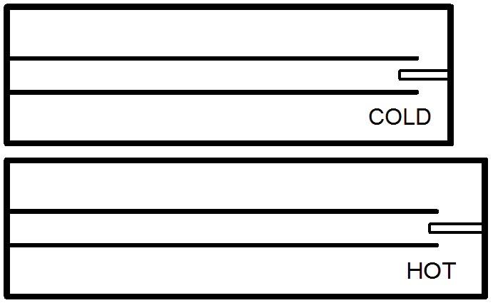
Figure 4-2: Temperature stabilization
If we allow a short metal rod to extend a short distance into the open end of the center conductor, we implement temperature stabilization. How? Quite simply. The small rod is attached to the opposite end of the cavity as the center conductor. As the cavity expands the short rod naturally tends to withdraw. It does so in that the outer wall of the cavity is longer than the center conductor. Further, if we make the outer wall of a metal that expands more rapidly, the effect will be greater. This is the case for our sample cavity. The inner conductor is made of copper and the outer wall aluminum. Aluminum expands more rapidly than copper.
How does this arrangement minimize frequency drift? The end of the center conductor and the rod make up a small capacitor that is in parallel with natural capacitance of the cavity. Recall that a resonant cavity act as if it were made up of discrete coils and capacitors, So in other words, the little rod "tunes" the cavity a small amount. The colder the cavity become the more the rod withdraws, thereby lowering the frequency, just as we want. The opposite takes place at warmer temperatures. The small rod, which I generally make from a threaded 1/4 in brass bolt and a captive nut or a threaded hole, also provides, as a secondary benefit, a convenient way to make small adjustment to the overall tuning of the cavity. NOTE: The screw is designed to function correctly when it is screwed in half way. If you discover that you must move it near its ends to tune the cavity, change the length of the center conductor a small amount.
How long should you make the small rod, and how much shorter must the center conductor be to compensate for the presence of the rod? Unfortunately these are not simple to calculate. Like a good ham, I prefer a pragmatic approach. During the design phase of a cavity I first shorten the center conductor a little and introduce the bolt, screwed in half way. Then I retune the cavity to frequency by shortening the center conductor a small amount.
Next I perform a rough measurement of how much the cavity drifts with changes in temperature. A large cardboard box and a common hair dryer are quite adequate tools to accomplish this. If the resonant frequency still drops at higher temperatures, I install a longer bolt and shorten the center conductor a little bit more. After a few such adjustments I arrive at a reasonable value. Remember you don't have to get it perfect. The temperature drift of commercial Invar rod stabilized cavities isn't perfect either. All you need do is to reduce the temperature drift enough so that the notched frequency remains within the bandwidth of the notch. The dimensions given for the bolt and the center conductor of the cavity in this book satisfy these requirements for this cavity.
Duplexer cavities again are not black magic. The home builder can achieve very acceptable temperature stability for home-brew cavities with this simple but elegant little method. I have used it successfully on most ham VHF and UHF bands.
Contact Information:
The author can be contacted at: jportune [ at ] aol [ dot ] com.
Back to the top of the page
Back to Book Index page
Back to Antenna Index page
Back to Home
This article created on Wednesday 09-Jan-2019.
Article text, images and photographs © Copyright 2019 by John Portune W6NBC.
Layout and conversion to HTML © Copyright 2019 by Robert W. Meister WA1MIK.
This web page, this web site, the information presented in and on its pages and in these modifications and conversions is © Copyrighted 1995 and (date of last update) by Kevin Custer W3KKC and multiple originating authors. All Rights Reserved, including that of paper and web publication elsewhere.