Antenna Index page
Home page
Let's Make a Cavity
By John Portune W6NBC

|
Book Index page Antenna Index page Home page |
Cavity Duplexers Chapter 2 Let's Make a Cavity By John Portune W6NBC |
|
We'll step aside in this early chapter for a do-it-yourself project and build an actual working 2M cavity. It's practical for two reasons. It will make the remaining chapters easier to illustrate. If you will build one and experiment with it, you will gain the kind of practical knowledge most repeater owners' lack. This is how I acquired mine. I highly recommend the process.
You can also, if you wish, use several of them to build an actual working 2M duplexer. This cavity is a bandpass (Bp) cavity. We'll learn about cavity types and how to change this cavity into a notch (Br) cavity later. You can also scale these cavities up or down for another band.
Construction Objectives:
When I built my first duplexer I had two objectives. They're still the same today. First I wanted to use only hardware-store materials and home-workshop techniques. Published home-brew designs often discourage would-be builders with hard-to-get or expensive materials, and often the need for machine-shop facilities. This design uses neither.
Second, the cavity(s) had to be easy to tune. Here you'll only need a thru-line wattmeter, a couple of dummy loads suitable for the frequency, and an ordinary synthesized HT or mobile transceiver on the band. Any of the common ham antenna analyzers is also useful. If you just happen to have access to a spectrum analyzer or a vector network analyzer with a tracking generator, all the better, but it isn't necessary. These just make things easier.
Materials and Special Tools:
The first decision in building a cavity is the type of metal to use. As any home craftsman knows that there are not many choices, steel, stainless steel, brass, aluminum and copper. For low insertion losses, copper is by far the best. What's more, it solders easily. But copper is expensive. In recent years it has become almost prohibitive. That's why commercial duplexer manufacturers often use aluminum. The losses are just a little higher and aluminum does present fabrication problems for the home builder, but these are manageable in the home workshop.
In case you are wondering, steel is unsatisfactory. Number one, it rusts. More importantly, it has very poor conductivity compared to copper or aluminum. See Table 2-1. A steel duplexer would have very high insertion loss. Stainless steel is also of no interest either. It too has low conductivity.
Some commercial manufacturers use silver-plated steel, but electroplating is generally impractical for home builders. Common yellow brass, as Table 2-1 illustrates, is also not a good choice, again because of relatively low conductivity. Red brass, which has much a higher percentage of copper, can be used.
| Silver | 1.0 |
| Copper | 1.1 |
| Gold | 1.4 |
| Aluminum | 1.6 |
| Nickel | 4.3 |
| Brass | 5.0 |
| Iron | 6.3 |
| Tin | 6.9 |
| Lead | 14 |
Table 2-1: Relative resistivity of common metals
A curious point here is that gold is a poorer conductor than copper. Gold is used on electronic connectors because of corrosion resistance, not high conductivity.
Copper is the most workable choice for home-brew cavities, particularly common hard-drawn household copper water pipe. It solders easily and excellent ends caps are readily available in all pipe sizes. These eliminate the need for machining. That's why I chose common copper water pipe for my early duplexers. Today, however, copper has become almost prohibitive for the home duplexer builder at all but UHF.
Aluminum is to me the best choice for home brew 2M and 220 MHz cavities and duplexers. True, aluminum cannot be soldered and there are no available end caps as with common copper water pipe. But as you will see, there are easy ways around these.
Also, is slightly lower conductivity than copper is not enough to make aluminum unsatisfactory. One just needs to make the cavities slightly. Aluminum is, therefore, the material we'll use for an example cavity.
Connectors:
The second decision is the connectors used to connect the cavities to a repeater or between cavities in the duplexer. I universally recommend BNC connectors. N-type are also excellent, but are more expensive and not really necessary for most repeaters, which are generally under roughly 100 Watts. Common PL/SO-239 connectors are just barely okay for 2M and below but are quite poor at UHF.
Commercial Cake Baking Pans:
Now for my "big trick." This is how I easily tamed aluminum for home brew. I was looking around a restaurant-supply store one day and noticed some heavy-duty round commercial aluminum cake-baking pans. They have nearly vertical sides, are about 2 inches high and come in diameters from seven to twelve inches. And, they are reasonably priced. "Here are the end caps I have been looking for to make aluminum cavities."
I then remembered that hardware stores sell flexible, 10 mil (thin) hard-alloy aluminum sheet in rolls. It was obvious that a sheet of this could easily be wrapped around two commercial aluminum baking pans (bottoms facing) and held in place with stainless steel hose clamps. The end result would be an excellent aluminum cavity, easily made in a home workshop. If you can't find stainless hose clamps long enough, simply use several to form one longer clamp.
The example cavity shown below is made from the smallest commonly available cake pan size (7 in.).
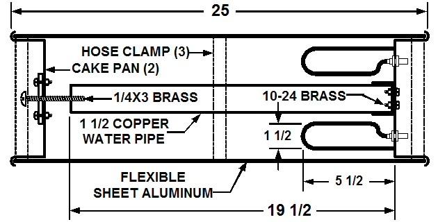
Figure 2-1: Cross section of 2M sample cavity
If you are contemplating 6M or 10M cavities, larger cake pans are ideal. I have used 11 in. cake pans on these lower-frequency bands. Frankly, even at 2M, larger diameter cavities perform better. Use them if you have the room. There is, however, a size limit, which we will see later.

Figure 2-2: Example 2M cavity and loop detail
The center conductor here is a 1/4 wavelength length of 1 1/2 inch common copper water pipe with an end-cap to make attachment to the end of the cavity easy. We'll learn later how to select the diameter of the center conductor for other bands or larger cavities.
Here the coupling loops are made from ordinary 3/16 in. soft-drawn copper tubing. The connectors are chassis-mount BNC jacks, fitted with long ring-type grounding lugs.

Figure 2-3: Center conductor extension and tuning screw
Tuning the Cavity:
To tune the cavity and its loops, only a simple setup is needed. The transceiver needs to be modified to transmit outside of the ham bands so that you can cover more than the ham band during the initial design phase.
Tune-Up Procedure:
Here's the basic cavity-tuning process. It is much the same as we'll also use to tune up a complete duplex later.
First connect one port of the cavity (either connector) to your transceiver and on the other side a through-line Wattmeter and a dummy load. The dummy load MUST be specified for at least the frequency on which you are working. If you happen to have a spectrum analyzer with a tracking generator, connect the tracking generator to one connector and the analyzer to the other. Figure 2-4 shows both setups.

Figure 2-4: Cavity tune-up setups
For the basic setup, in small frequency steps, apply power briefly and record the Wattmeter reading. Power throughput will peak at the cavity's resonant frequency. Plot the data on a graph. The graph wizard in Microsoft Excel is an excellent tool for this, though a paper graph is completely satisfactory. It will immediately show you the frequency to which the cavity is tuned, as well as its overall frequency response, and the insertion loss (space above the curve). See Figure 2-5. This is the basic tuning procedure used for design and in the field, for individual cavities and complete duplexers. No other tools are needed.
If the graph shows that the cavity is quite a bit off frequency, you will now need to lengthen or shorten the center conductor. The tuning screw shown in Figure 2-3 is only for fine-tuning.
To raise the resonant frequency, shorten the center conductor in this cavity by roughly 1/4 in. per Megahertz. To lower it, lengthen the center conductor. An easy way to do this without installing a new center conductor each time is to fabricate a slip-on extension from a short piece of the same-sized pipe, slit lengthwise down one side. I cut the slit with a hand-held hobby grinding tool and a cutoff disk. Pry the slit open with a large screwdriver until the extension fits snugly over the end of the center conductor. You can solder the extension in place if you wish after tuning, or replace the entire center conductor.
This configuration naturally creates a bandpass (Bp) cavity. Bp cavities have the response shown in Figure 2-5. Our sample cavity here has a power bandwidth of roughly 2.5 MHz and an acceptable small amount of insertion loss. Later we'll modify it to form a band-reject (Br) or notch cavity. By building several cavities and following the guidelines given in the remainder of this book, you will be able to assemble a complete 2M duplexer.

Figure 2-5: Frequency response (Bp) of sample cavity
Actually building and then experimenting with a cavity like this was the most instructive part of the entire duplexer adventure. Hilltop experience does not even come close. Try it. You will not regret it. If nothing else, you will at least find out that duplexers are not black magic.
Contact Information:
The author can be contacted at: jportune [ at ] aol [ dot ] com.
Back to the top of the page
Back to Book Index page
Back to Antenna Index page
Back to Home
This article created on Wednesday 09-Jan-2019.
Article text, images and photographs © Copyright 2019 by John Portune W6NBC.
Layout and conversion to HTML © Copyright 2019 by Robert W. Meister WA1MIK.
This web page, this web site, the information presented in and on its pages and in these modifications and conversions is © Copyrighted 1995 and (date of last update) by Kevin Custer W3KKC and multiple originating authors. All Rights Reserved, including that of paper and web publication elsewhere.