Back to Home

|
Up one level Back to Home |
An Article by Tony King W4ZT |
|
Using Andrew FSJ1-50A 1/4" Superflex Heliax with PL-259 Connectors
| http://w4zt.com | http://w4zt.com/repeater/duplexer/superflex/ |
| This project began as an effort to make new jumpers for an older Phelps Dodge duplexer. All six of the original jumpers were each 8-3/4" long (but don't take that as gospel, measure yours and use that measurement). Following are the details of how the PL-259 connector is installed on the Superflex. Each photo is a thumbnail and will enlarge to a full size photo. Click on the "Back" button of your browser to return here. | |
|
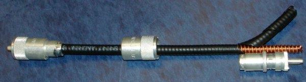
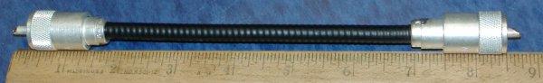
1 |
This photo shows a single 9" length of FSJ1-50A 1/4" Superflex Heliax with one connector installed. The following steps will install a matching connector on the other end. |
|
2 |
Use Teflon silver plated PL-259 connectors for ease of soldering and because nickel plated connectors have been proven to cause problems at VHF and UHF. In this example, the jumper needed to be 8-3/4" long. I cut a piece of cable 9" long by simply cutting with a pair of lineman's pliers. |
3 |
Prepare the end of the cable by measuring the distance from the end of the cable to the end of a UG-176/U which is normally used when installing a PL-259 on RG-59 sized cable. |
4 |
I used a sharp Leatherman knife blade to score the jacket around and then a tapered cut all the way to the end so the jacket could be peeled off. |
5 |
Be sure to put the outer shell of the PL-259 on the cable NOW to avoid forgetting it later. |
6 |
Use pliers to mash the end of the cable back to round so you can push the UG-176/U over the end and against the jacket of the Superflex. With the UG-176/U in place, score the spiral groove of the superflex between the UG-176/U and the end of the cable with a sharp knife. |
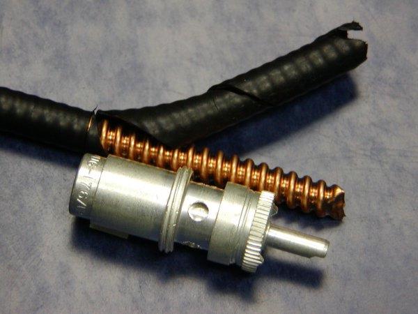
7 |
Use diagonal cutters to grab the end of the spiral and begin peeling it back around the dielectric until you reach the UG-176/U. |

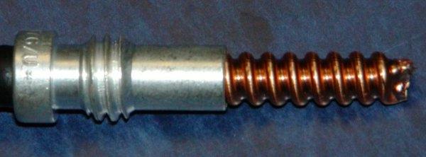
8 |
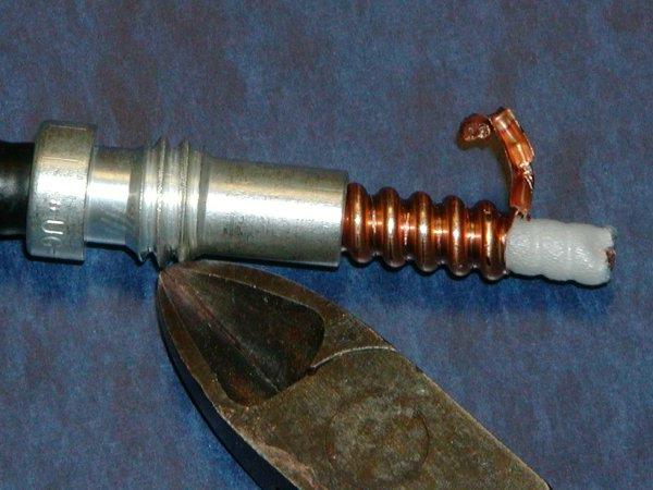
Cut the excess copper spiral off and flatten the end of the copper against the end of the UG-176/U. Cut the foam dielectric back from the end of the cable to within about 1/8" of the UG-176/U. |
9 |
Using a hot soldering iron, solder the copper spiral to the end of the UG-176/U. Also place a few solder points around the end of the UG-176/U to provide an easy way to solder through the connector body to. Cool the UG-176/U with a damp sponge. |
10 |
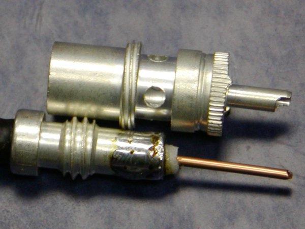
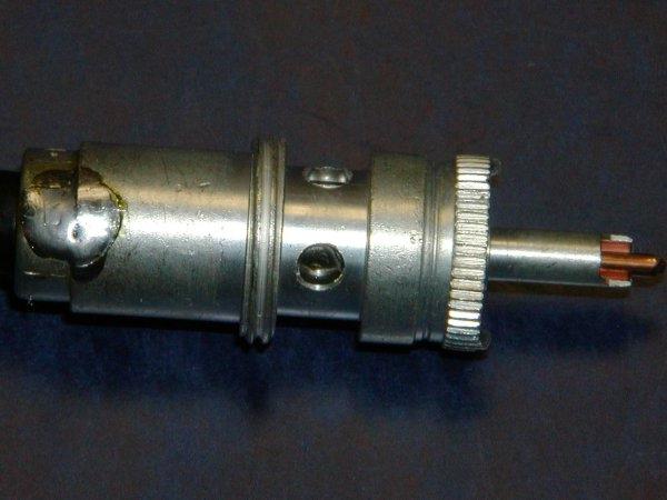
Screw the UG-176/U into the connector body and tighten with pliers. Solder the end of the UG-176/U to the connector body in one spot to prevent any possibility of it turning. Cut the 1/8" remaining center conductor off even with the end of the connector center pin. |
11 |
Solder the center pin. Solder through two opposing holes in the connector body to insure a positive electrical connection between the UG-176/U and the connector body. Be careful in this step to get a good solder joint but not to overheat the connector. After each soldering operation, cool the connector against a damp sponge. |
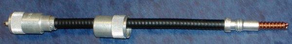
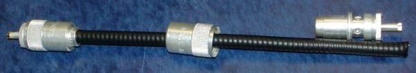
12 |
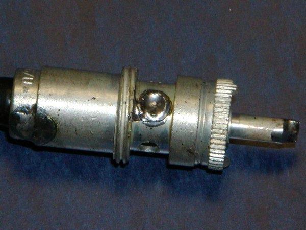
Screw the outer shell onto the connector body.
Measure your jumper to insure you have the correct length. You're done! |
Back to the top of the page
Up one level
Back to Home
Original article text and photos are © Copyright 2007 by Tony King W4ZT, All Rights Reserved
Mike WA6ILQ of Repeater-Builder edited some text, simplified the original HTML, and added
a credit line to Tony.
Originally posted 01-Sept-2007.
This web page, this web site, the information presented in and on its pages and in these modifications and conversions is © Copyrighted 1995 and (date of last update) by Kevin Custer W3KKC and multiple originating authors. All Rights Reserved, including that of paper and web publication elsewhere.