Home page
By John Haserick W1GPO

|
Up one level Home page |
Building a 440 MHz Z-Match
By John Haserick W1GPO |
|
Background:
A Z-Match is nothing but a pi-network matching device to tune a transmitter to a feed-line or load. It is useful if either the transmitter has fixed output tuning that is not optimal, and/or if the load is not 50 ohms purely resistive. A properly constructed Z-Match should have nearly 0 dB insertion loss on the operating frequency, so it is also useful to determine if a transmitter is operating at peak efficiency by measuring the transmit output into a 50 ohm dummy load, and then inserting the Z-Match between the transmitter and the load, then tuning the Z-Match for peak output. If both outputs are equal, then the fixed tuned transmitter is optimum.
Why We Needed One:
In our case we wished to use the 6M repeater antenna to also receive a nearby 6M receive site via a 440 MHz link transmitter. Our 6M repeater antenna is a 5/8 wave ground-plane with tapped base coil MUCH heavier duty, but similar to the Dominator converted Sirio 827 ground-plane by Norwalk Electronics. This requires a diplexer in the repeater cabinet to split the 6M and 440 MHz signals, but there is obviously a 440 MHz mismatch from the 6M antenna, so we built up the Z-Match to allow transmission back on 440 MHz with, it turned out, actually zero reflected power from the 440 MHz transmitter. We were lucky in that the Z-Match tuning capacitor ranges were adequate. If that were not the case, different lengths of coax would have to be tried between the diplexer and the Z-Match. The link radio's transmitter was used for test purposes.
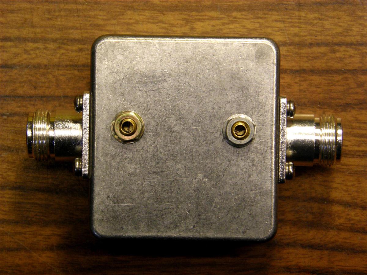
Here's the outside of the Z-Match with the piston trimmers clearly visible.
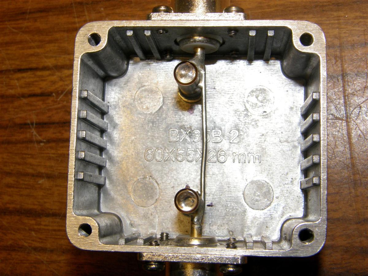
Here's the inside of the Z-Match.
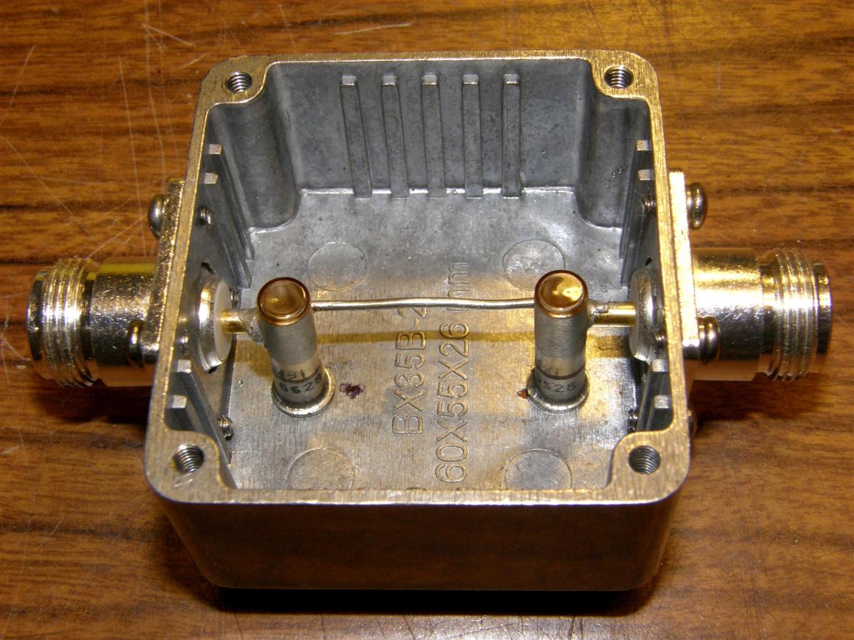
And another view of the inside.
Construction:
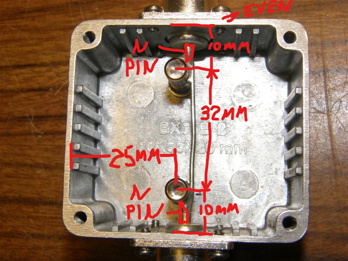
The connectors go on the long sides, in the areas where the internal ribs are missing. Use a 1/2 inch hole punch, not a 1/2 inch drill, so you get nice clean smooth holes. Bevel the outside edges so the N connectors fit fully into the box. Make it so the top edge of each connector is flush with the top edge of the cast box. The capacitors are offset from the centerline 1mm to the left (see photo below) and are centered 10mm from the inside of the box. The wire is 50mm long and fits inside the N connector's center pins. The points of the N center pins almost touch the caps, but are offset about 1mm to the right of the cap centers. Place the connectors before drilling the holes for the caps. Make those holes a snug fit. The photo below has dimensional measurements.
Tuning the Z-Match:
To tune up the Z-Match, place a wattmeter between the load and a 440 MHz transmitter and tune the Z-Match for minimum reflected power. If there is near zero reflected, then the wattmeter is seeing a flat 50 ohms so that when it is removed, the transmitter should see the same match. If not near zero reflected, change the feed-line length to the wattmeter from the load until that occurs. Then never change anything in the antenna, duplexer, diplexer, etc. in the feed-line side of the Z-Match without retuning the Z-Match.
Results:
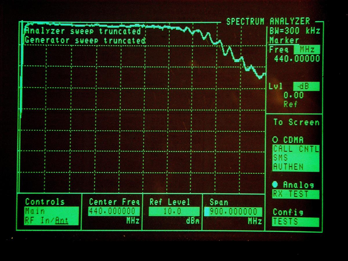
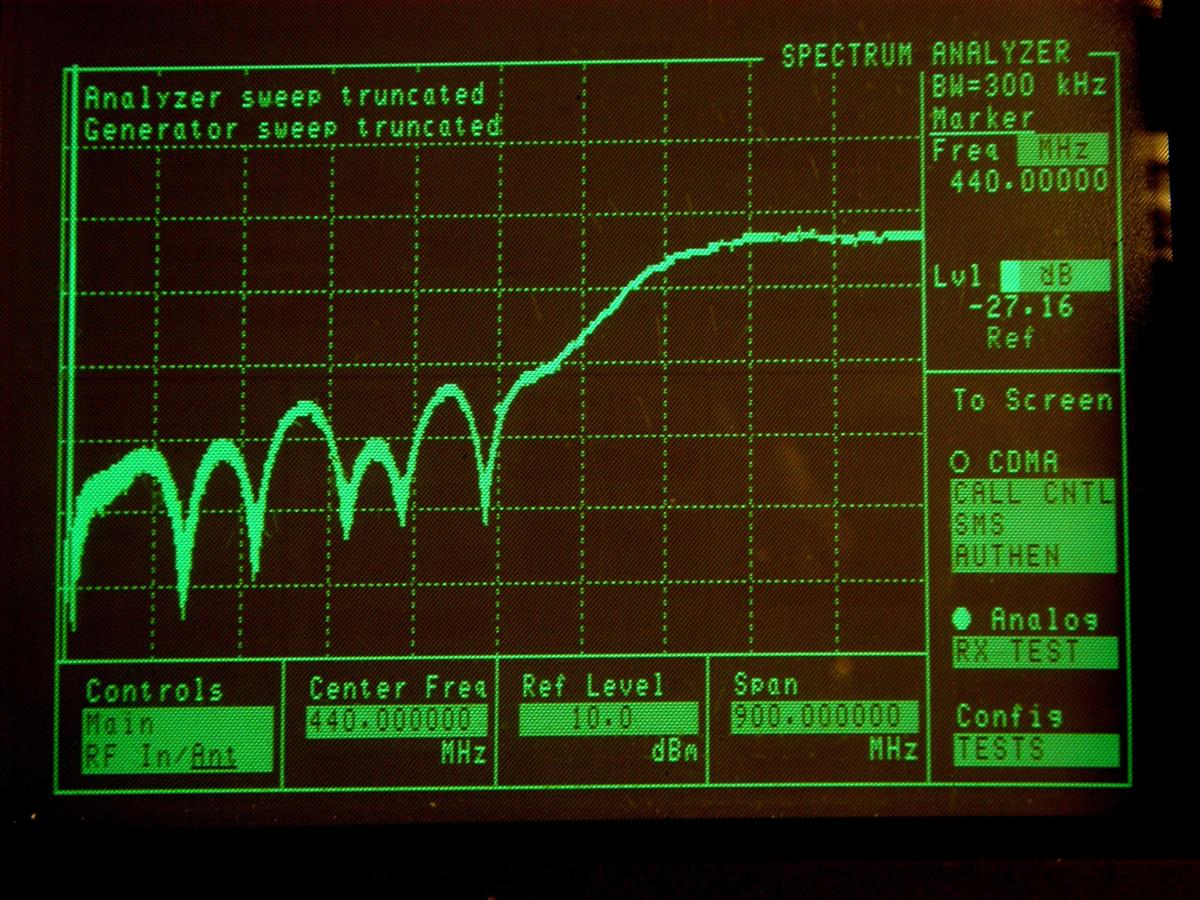
The Z-Match is also somewhat of a low pass filter with good attenuation at about twice the desired operating frequency and above. Pass loss is close to 0 dB. The trace shows more, but that is due to about a total of 12 ft of RG-400 test leads increased loss with frequency, as loss was measured with reference N barrel in place of the Z-Match. The return loss is about -27dB at the operating frequency. The Z-Match is best inserted between the feedline termination and the diplexer to permit the best diplexer isolation performance, as it has very minimal effect on SWR or insertion loss on 6M, but does improve isolation a few dB.
Here's a spectrum trace showing the minimal pass loss below about 440 MHz.
Here's a spectrum trace showing the return loss (a measurement of matching efficiency) around 440 MHz.
This Z-Match was optimized for operation around 435 MHz. For higher frequency use, there would need to be less inductance, so maybe a strap would have to be used instead of a round wire.
Measurements of Return Loss and Insertion Loss at other frequencies are summarized below.
420 MHz: RL = 37 dB, IL = 0.32 dB
430 MHz: RL = 30 dB, IL = 0 dB
440 MHz: RL = 27 dB, IL = 0 dB
450 MHz: RL = 23 dB, IL = 0.36 dB
Parts Used or Required:
Credits and Acknowledgements:
All photos were taken by the author and are copyrighted by him.
Thanks to Bob WA1MIK for turning this into an article suitable for publication.
Contact Information:
The author can be contacted at: jhaserick84 [ at ] comcast [ dot ] net.
Back to the top of the page
Back to the Antenna Systems Index page
Back to Home
This article created on Sunday 04-Jun-2021
Article text and photographs © Copyright 2021 by John Haserick W1GPO.
Conversion to HTML and some text © Copyright 2021 by Robert W. Meister WA1MIK.
This web page, this web site, the information presented in and on its pages and in these modifications and conversions is © Copyrighted 1995 and (date of last update) by Kevin Custer W3KKC and multiple originating authors. All Rights Reserved, including that of paper and web publication elsewhere.