Antenna Index page
Filter Design
Part Of An Entire Duplexer
By Tim Ahrens W5FN
Turned into an article by Robert W. Meister WA1MIK

|
Home page Antenna Index page |
Another 6-meter Heliax Filter Design Part Of An Entire Duplexer By Tim Ahrens W5FN Turned into an article by Robert W. Meister WA1MIK |
|
Tim built up several Heliax coax filter sections per Bob's article. He tried making a full duplexer out of them, with multiple sections notching the TX frequency on the receive side, and multiple sections notching the RX frequency on the transmit side. He soon found out that the piston trimmer capacitors were totally inadequate for use on the transmit side, where all the RF power is. After several attempts and discussions, he came up with a rather simple design for a high-power, small value variable capacitor made with a piece of RG8 coax and a short brass tube. He sent me some drawings and I turned them into this article. Read the notes on the drawings as they offer additional details. Although some of the other Heliax filters and duplexers also use a brass tube design, the tuning mechanism described here was conceived before he was aware of the efforts by others.
All of the work and design for this tuning mechanism is Tim's; he gets all the credit. Direct all questions to him; his contact information is at the end of the page. Click on any of the images for a larger view.
Tim's Setup:
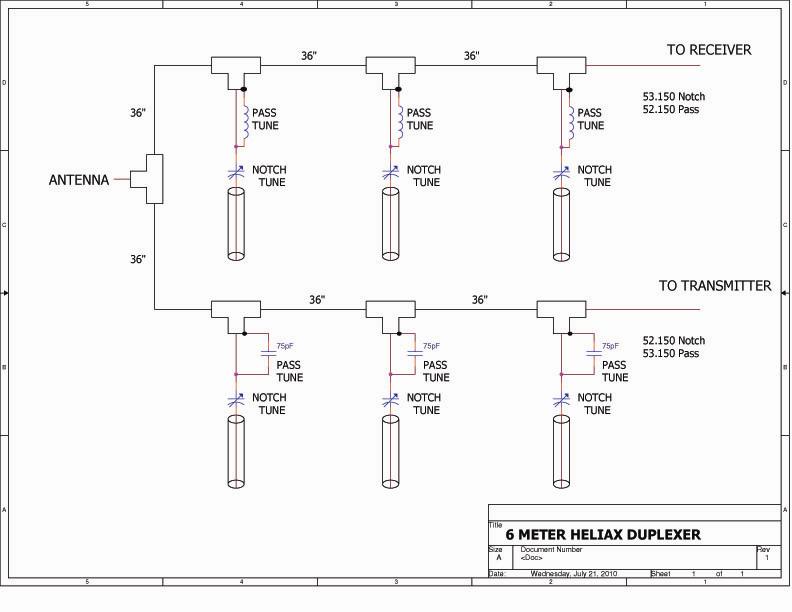
The repeater transmit frequency is 53.150 MHz. The transmit cavity lengths are 41 inches. They are notching 52.150 MHz.
The repeater's receive frequency is 52.150 MHz. The receive cavity lengths are 39-1/2 inches. They are notching 53.150 MHz.
The bottom end of each Heliax cavity has crossed pieces of 1/2" brass soldered to the center conductor and outside copper. (Tim was lucky; the Heliax he used had copper for both the inner and outer conductors.)
All cavities exhibited pretty much the same characteristics: 30 to 32dB notch and 0.4 to 0.6dB insertion loss. The final three-cavity setup gave provided about 104dB notch and 1.6dB insertion loss. Here's an accurate schematic diagram of his duplexer.
A High-Power Variable Capacitor:
This design mostly concerns itself with the top end of the filter and the tuning capacitor. A piece of thin-wall brass tubing 9 inches long, 0.351 inches outside diameter, and 0.310 inches inside diameter is soldered inside the hollow center conductor of the piece of Heliax coax. This will be the outer conductor for the tuning capacitor. See figure 1 in the drawing below.
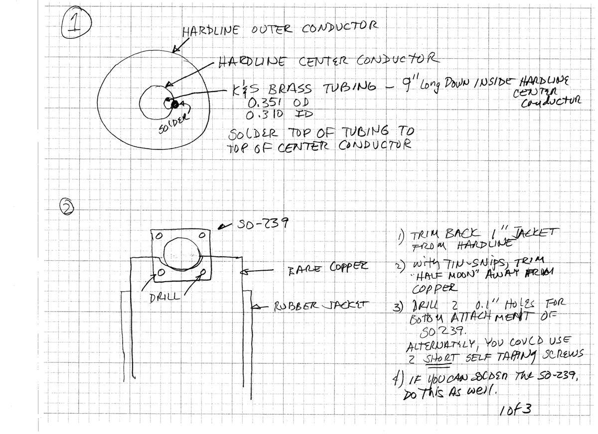
Tim used UHF female connectors (SO-239) and mounted them to the side of the Heliax. See figure 2 in the drawing above.
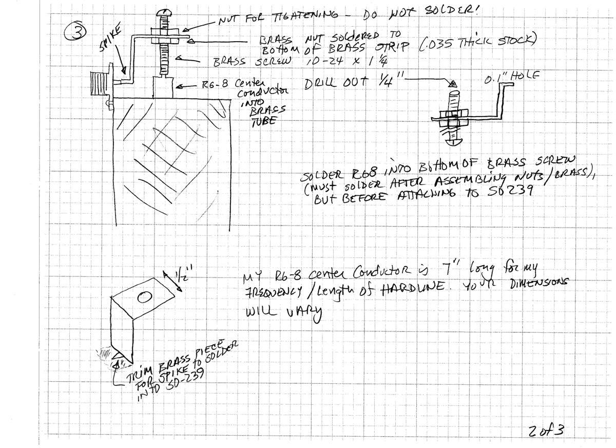
The inner conductor of the capacitor is made from the center conductor and insulation from a piece of RG8 coax, about 7 inches long. This is soldered to a brass machine screw that is threaded through a nut soldered to a support bracket. This becomes the tuning mechanism and it allows for a very fine adjustment of the insertion depth of the RG8 coax section. The center conductor of the RG8 coax is soldered into a 0.1 inch diameter, 1/4 inch deep hole drilled into the bottom of the screw. When the screw is turned, the entire piece of RG8 coax rotates but also moves up and down inside the brass tube. The construction details can be seen in figure 3 in the drawing below.
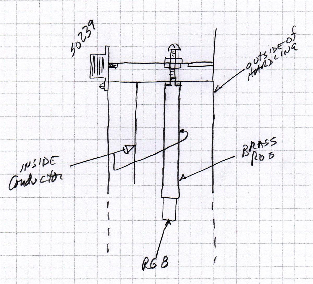
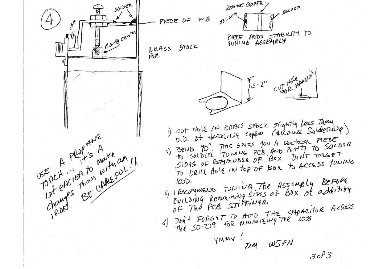
Tim revised the screw's mounting bracket and how the RG8 fits into the brass tube. The text and diagram below shows the details of this revision.
I used a thin strap - about 1/4 inch wide - of brass straight out of the SO-239, and attached it to the opposite wall the same way as with the first bracket. I drilled a hole directly above the brass tube. This time however, all of the 'plunger' action will go on inside the brass tube on the top. The RG8 center conductor and insulation will extend below the bottom of the brass tube. The RG8 will be same length, but the brass tube will be cut down 1 inch shorter than the RG8; in the first version the extra inch of RG8 was above the tube. The brass tube is 6 inches long, the brass screw is 1.25 inches long, and the RG8 pigtail is 7 inches long, not including the solder tab.
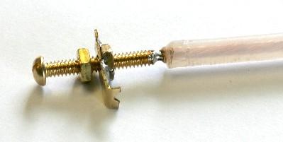
Here's a photo of the revised screw, bracket, and center section of RG8 soldered to the screw:
The support bracket connects to the center terminal of the coaxial connector mounted to the side of the Heliax. The other end of the bracket is supported through an insulated piece of circuit board to another bracket that's attached to the top of the Heliax. After tuning, additional pieces of metal were attached to the sides of the brackets to provide a lot more shielding. Figure 4 in the drawing below shows a more complete view.
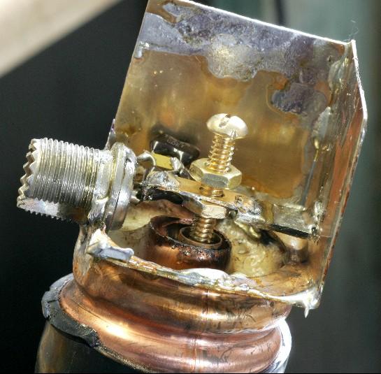
Here's a photo of a completed top section with one side removed (or yet to be attached), showing all of the pieces:
As these sections are used for the transmit side, they need to minimize the pass-band loss. As such, a small fixed capacitor is soldered to the back of the SO-239. These serve the same purpose as the coils attached to the back of the connectors on the receive filter sections, which notch the transmit frequency. This is mentioned in the notes on the above drawing.
Tim adds the following as an aid to getting the notch tuning just right:
When adjusting the notch tuning capacitor, I first screwed the RG8 all the way in to the tubing, and measured (on the spectrum analyzer) where the notch was. Then I unscrewed it all the way out, and noted the notch frequency. From that, I could determine how much of the RG8 to cut off to put the desired notch directly in the middle of the mechanical tuning range. (Gee, I cut it three times, and its still too short!) If you make a mistake in the length of the RG8, at least it's easy to get, and cheap!
Contact Information:
Tim can be contacted at: tahrens [ at ] swtexas [ dot ] net.
Back to the top of the page
Back to Home
Back to Antenna Index page
This page originally posted on Tuesday 20-Jul-2010
Diagrams and design idea Copyright © 2010 by Tim Ahrens W5FN.
Article text and HTML Conversion copyright © 2010 by Robert W. Meister WA1MIK.
This web page, this web site, the information presented in and on its pages and in these modifications and conversions is © Copyrighted 1995 and (date of last update) by Kevin Custer W3KKC and multiple originating authors. All Rights Reserved, including that of paper and web publication elsewhere.