
An Introductory Tutorial by
The Jack Daniel
Company
Copyright 1996-2005 Jack Daniel Company
WHY ARE DUPLEXERS USED?
Radio receivers can be damaged if high
level RF signals, like those directly from a transmitter output, is applied to
the receiver antenna.
Additionally, receivers may become 'desensitized' (or 'de-sensed') and not receive weak signals when high noise levels or another signal near the receive frequency is present at the receivers antenna input.
Obviously, radio receivers and transmitters cannot be directly connected to
the same antenna without some device being used to:
(1) switch the antenna
between the transmitter and receiver so that they are never connected to the
same antenna at the same time.
(2) When the transmit and receive frequencies
are different, filters may he used to reduce the transmit signal levels to an
acceptable low level at the receivers antenna input. Naturally, you cannot
filter out the transmitter signal when it is the same as the receiver
frequency.
Definition of a duplexer:
A device which allows a transmitter
operating on one frequency and a receiver operating on a different frequency to
share one common antenna with a minimum of interaction and degradation of the
different RF signals.
Duplex Operation
Duplexers are often the key component that allows
two way radios to operate in a full duplex manner. Full duplex means the
transmitter and receiver can operate simultaneously as opposed to the
'push-to-talk' manner used in non-duplex (or 'simplex') operating modes.
Remember, The radio system must use two frequencies per 'channel' to use the kinds of duplexers we are discussing.
Recently, some very specialized digital radio systems that are under development are emulating duplex operation by switching the transmitter and receiver off and on extremely rapidly. This is not real full duplex operation but appears similar to the radio users. This discussion does not address this approach, but instead deals with more common accepted land mobile practices.
Duplexers are the devices that allow a mobile telephone to operate like a wired telephone, with either or both people speaking at any time without using a microphone switch to enable the radio transmitters.

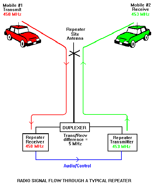
The duplexers at repeaters may serve several objectives:
WHY NOT USE TWO ANTENNAS?
Two antennas may be used instead of a
duplexer, provided the antennas are placed far enough apart that the transmitter
signals do not interfere with the receiver. Two transmission lines will also be
required.
The isolation required between the transmitter and receiver is a complex issue and influenced greatly by the specific transmitter and frequencies used, the bandwidth of the channel, the difference in frequencies of the two frequencies to be used and the minimum amount of receiver degradation that is acceptable to the user.
It is not unusual to have a radio system require as much as 80 to 100 dB isolation between the transmitter output and the receiver input.
When two antennas are used, the type of antennas, the physical spacing and the orientation of the antennas to one another are also major concerns.
The antenna to antenna isolation can also be influenced by the presence of other antennas on the same tower as well as other nearby transmitters and mechanical structures. These factors may change over time and be out of the control of the repeater operator.
Antenna separation designs should also consider any additional receiver protection that may be required for other transmitters that may be present on the same tower.
In some extreme cases, duplex filters AND antenna separations may both be required to obtain satisfactory operation. This generally only occurs at lower frequencies with small differences between the transmit and receive frequencies or when closely spaced channels are combined.
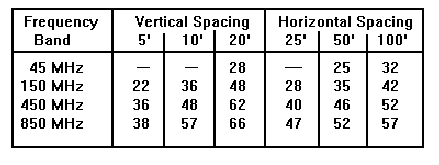
Typical Antenna Spacing Isolation Values: (In dB) (Based on vertically polarized half-wave dipoles. Actual experience will vary due to local conditions, antenna variations, etc.)
TYPES OF FILTERS USED IN DUPLEXERS
There are several
ways to implement a duplexer, but all rely upon the characteristics of different
types of RF filters. Specifically:
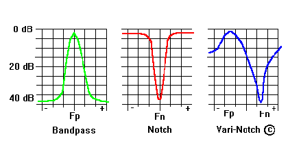
- Bandpass filters which allow a specific range of frequencies to pass through them. The filters are designed and tuned to a specific 'center frequency' and 'pass band' with relatively low losses to desired frequencies and higher losses that increase as the deviation from the center frequency increases.
- Reject or Notch filters which operate opposite of a bandpass filter. These are designed to cause high losses at the center frequency and lesser losses as the frequencies increase from the center frequency.
- Specialized filters such as TX RX Systems "Vari-Notch" (c) filter, which has characteristics of both a bandpass and notch filter in one device.
The filters are usually tubular or square cavity type filters but other types of construction such as combline, ceramic, etc. may also be used in some cases.
Cavity type filters offer the best overall balance of performance, simplicity and costs.
Combline and ceramic filters have some space and size advantages at higher frequencies.
Ceramic filters may have power limitations and higher cost.
Although this discussion centers on the more commonly used cavity type filters, the basic principals will apply to any type of filter used in duplexers.
DUPLEXER AND FILTER TERMINOLOGY
Decibel (dB):
A decibel is a logarithmic scaling value
that is used in most RF engineering work because of its universal acceptance and
simple manipulation in calculating signal and power levels. A decibel is a
relative number, not an absolute value.
For example, a +20 dB difference in a power level is the same as saying the level change is 100 times the starting value. If the change was -20 dB, the change would be 1/100th the original level.
Decibel/one milliwatt (dBm):
This signifies an absolute
(real) value, with 0 dBm being one milliwatt of power.
TX RX Systems provides a dB chart in their engineering catalogs.
Selectivity:
Selectivity is a measurement of the
ability of the filter to pass or reject specific frequencies relative to the
center frequency of the filter. Selectivity is usually stated as the loss
through a filter that occurs at some specified difference from the center
frequency of the filter.
For example; "- 3 dB bandwidth is +/- 250 KHz." means the output level of a signal frequency at + or - 250 KHz from the center (tuned) frequency of the filter will be at least 3 dB less than the level of the same signal IF it was at the center frequency.
The greater the selectivity the greater the attenuation of frequencies other than the center frequency.
The greater the selectivity the narrower the lowest loss 'window" of the filter and the need for good temperature and mechanical tuning stability in the filter design.
The larger the diameter of a cavity filter the greater the selectivity, assuming similar materials and construction of the filters being compared.
Tuning Stability:
Tuning stability is the ability of
the filter to remain at tuned at the desired frequency over time and variations
in temperature, orientation and vibration. Many aspects of filters are designed
to overcome these variables, such as the use of temperature compensating metals,
elimination of threaded tuning rods which can store mechanical torque stresses,
added cooling, fine tuning adjustments, etc.
Insertion Loss:
Insertion loss is the minimum amount of
loss to the signal passing through a filter at a designated frequency. For
example, a filter may have 1 dB insertion loss at its center frequency and if
two filters are used in series in a duplexer, the duplexers insertion loss would
be 2 dB.
Insertion losses occur in both the transmit and receive paths of a duplexer and they may be different amounts.
The greater the insertion loss, the less the output level.
Higher insertion losses generally increase the selectivity of cavity filters. (i.e. A filter bandpass might be +/- 200 KHz at 1.5 dB insertion loss and +/- 100 KHz at 2 dB insertion loss.
The greater the insertion loss, the greater the power dissipation and temperature rise of the filters. High insertion losses may reduce the power capacity of a filter.
Receiver Desensitization:
Receiver desensitization,
commonly called 'receiver desense', is caused when high RF signal levels enter a
receivers antenna input.
When desense occurs, the usual symptom is as though the desired signal was reduced; the signal becomes noisy or even fades out completely.
The frequency of the desensitizing signal can be considerably different than the frequency the receiver is tuned to. The interfering signal can be wideband noise and/or spurious emissions from the associated transmitter or other nearby transmitters.
The susceptibility of a specific receiver to off-frequency signals is dependent upon the receiver design and any external filtering added to the receiver.
Transmitter Noise:
Every transmitter emits signals
other than those on the desired frequency. The frequencies and amplitudes of
these undesired signals varies greatly and is dependent mainly upon the
transmitter design and the modulation used. The amount of transmitter noise can
be reduced by external filters and/or physical isolation between the transmitter
and any receivers.
TYPES OF DUPLEXERS
There are many ways to combine filters to perform duplexer operations. The more common approaches are:
Bandpass Duplexers:
Bandpass duplexers use several
filters to reduce the bandwidths of the transmitter output and the receiver
input frequency bands.
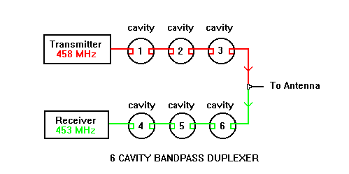
The amount of isolation between the transmitter and receiver may be reduced or increased by changing the number of cavities and the size (efficiency) of the cavities. Note that since the transmitter output passes through bandpass filters, therefore transmitter noise and spurious emissions are also attenuated in a bandpass type duplexer, which can help reduce interference to other receivers at the same site.
Bandpass type duplexers are best suited for moderate to wide transmit/receive frequency separations. Close spaced frequencies may require additional notch filters and/or separate antennas.
Notch Type Duplexers:
Notch type duplexers may appear
physically similar to bandpass duplexers but their operation and tuning is very
different.
There are two types of notch filters that may be used in a notch
type duplexer:
- The series notch filter, which has two ports (in and out).
- The shunt (or common) notch filter which has one port and is linked to the
other filter sections by a "T" connector. NOTE: Do not confuse this with the TX
RX Systems "T-Pass" filter which is a specialized bandpass filter.
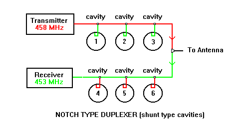
Cavities 1, 2 and 3 are tuned to notch out 453 MHz.
Less
than 1 dB loss near and at 458 MHz.
Cavities 4, 5 and 6 are tuned to notch out 458 MHz.
Less
than 1 dB loss near and at 453 MHz.
Cable lengths between cavity 3 and cavity 6 to "T" are tuned lengths.
Note that since the transmitter output passes directly to the antenna, therefore transmitter carrier and noise is only attenuated near the 453 notch frequency.
This offers minimal reduction of interference to other receivers at the same site.
Notch type duplexers are cost effective and operate at much closer transmit/ receive frequency separations than bandpass type duplexers.
Shared sites may require additional bandpass filters and/or separate antennas.
Bandpass/Band Reject (BP/BR) type duplexers:
These
types of duplexers are combinations of the two preceding duplexer types, having
many of the benefits of both and usually at some increase in cost. A
bandpass/band reject example; (Actual combinations vary widely)
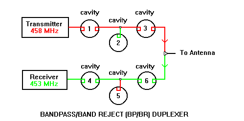
Cavity 1 and 3 tuned to pass 458 MHz
Cavity 2 tuned to notch
(reject) 453 MHz.
Cavity 4 and 6 tuned to pass 453 MHz.
Cavity 5 tuned
to notch (reject) 458 MHz.
Cable lengths between cavity 3 and cavity 6 to
"T" are tuned lengths.
The TX RX Vari-Notch (c) type Duplexer:
The Vari-Notch
type duplexer is a very popular, low cost and small size duplexer that is only
available from TX RX Systems. It is very similar to a bandpass/ band reject type
duplexer in operation and tuning.
The major difference is the use of TX RX Systems exclusive "Vari-Notch" (c) filter designs which incorporate the equivalents of a broad bandpass filter and a notch filter within the same cavity.
The result is the elimination of separate bandpass sections in most duplexer requirements and an inherent increase in the number of notch filters for a given number of cavities. It is important to remember that there can be interaction between the bandpass and notch frequency tuning of any combination duplexer, especially when the duplex frequencies are close spaced.
Additional details and technical notes about Duplexers, Filters and other
TX RX Systems products are available at www.TXRX.com.