Home page
V-6R 6-Meter Collinear
Gain Vertical Antenna
By John Haserick W1GPO

|
Antenna Index page Home page |
Improving the Hy-Gain V-6R 6-Meter Collinear Gain Vertical Antenna By John Haserick W1GPO |
|
V-6R Antenna Background:
Engineer Roger Cox did a wonderful job designing this antenna, and by the comparisons we have done, it is the highest performing of any manufactured 6-meter vertical antenna. Roger had mentioned to me that they did a range test of its identical design, which was either their 450 or 2 meter 5/8 over 3/8 ground plane, and found the main lobe was within 3 degrees of the horizon, very good considering the half power beam width is somewhere between 30 and 35 degrees. (By the way the 6m Ringo is the worst in this category!) Click on any photo for a larger view. Some of these files are quite big.
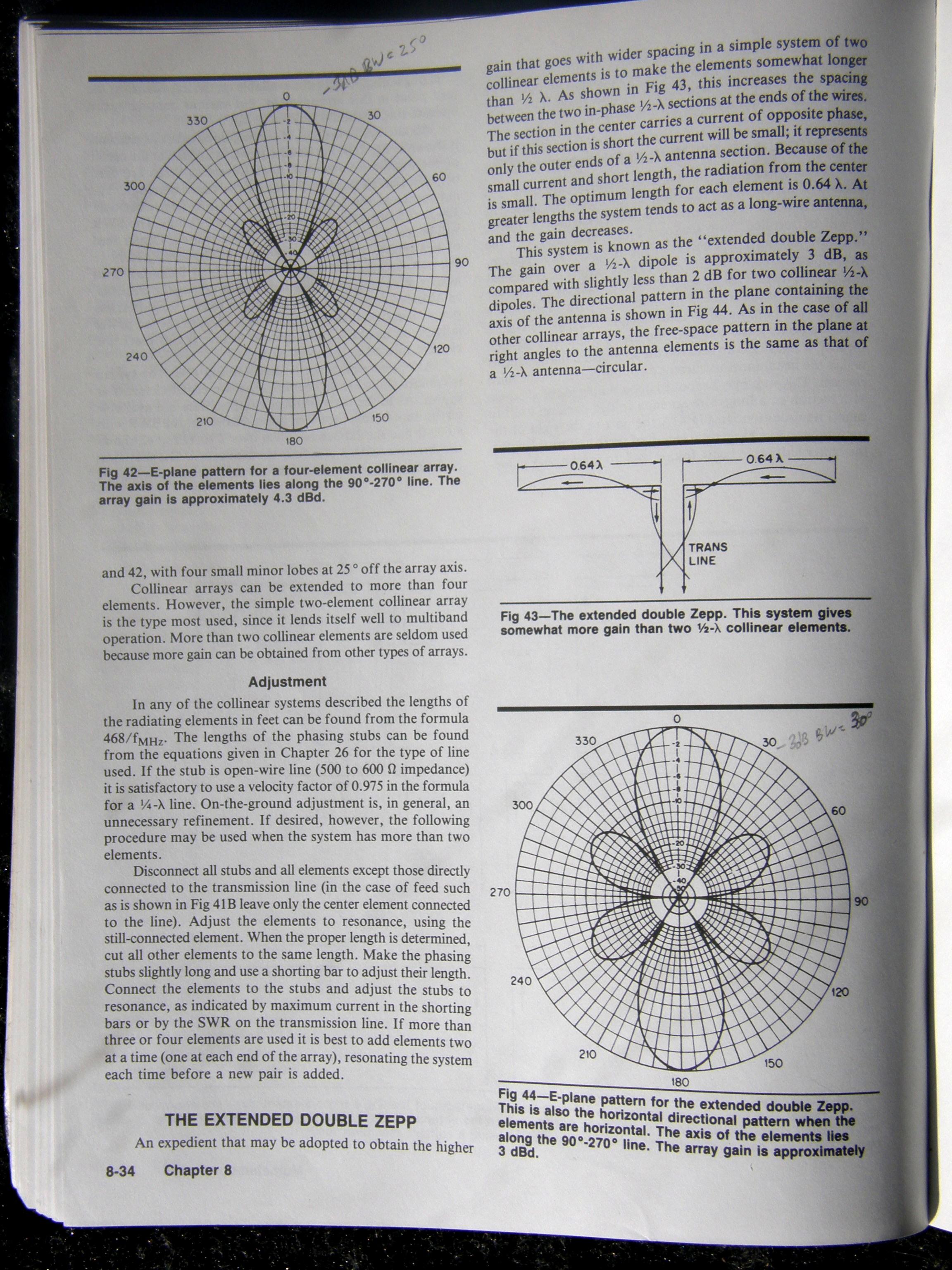
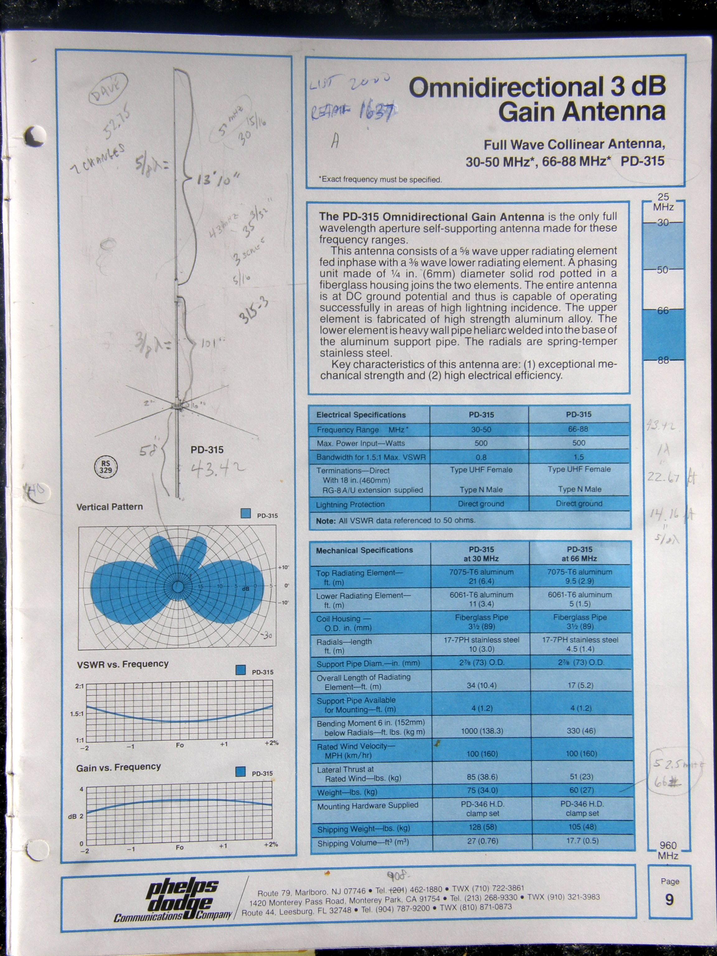
The extended double Zepp (see the page from ARRL Antenna Handbook above) has a 30 degree beam width, but if the lower element ends in a ground plane, the lower secondary lobe disappears, and the main lobe widens a bit if the ground plane radials are horizontal, and the four radials are each 5/16 wavelength long (70 inches at 53 MHz). Here's the datasheet for the Celwave PD-315 antenna.
The V-6R with the radials tilted down at 45 degrees needs to have the radials at 1/4 wavelength, because they are resonant with the antenna, whereas it appears to us that four horizontal radials are non-resonant, more just a reflective surface the antenna works against.
Mechanically, the V-6R could be improved by beefing up the aluminum parts, as the antenna is not above "amateur" in this category, due to amateur cost constraints. The high quality V-6R coil form is made of glass reinforced Noryl that is quite strong and rigid and may have a yield strength about half that of the aluminum tubing, so if there are parts of it under stress that are less than something like twice the thickness of the nearby aluminum tubing, that will be the mechanical weak point of the antenna. The coil form is the limiting factor as to how much the antenna can be strengthened. The weakest aluminum portion appears to be at the connection where the short 1-1/8 inch machined aluminum piece is protruding at the bottom where the coax connects, and the 1 inch OD, 0.058 wall tubing is hose clamped over it. Also this 1 inch OD tubing could be strengthened with 1-1/8 inch OD, 0.058 wall tubing over its entire length.
Electrically, the coil is #12 copper wire, 44 inches long, tapped 3-1/3 turns from the bottom with possibly #14 stranded, vinyl insulated wire to the top of the UHF barrel, the bottom of which is the antenna connection. There is wax on the top inside the machined aluminum piece that surrounds this jumper wire, and the wire is not precisely centered inside. Click here for the V-6R instruction manual as a 150kB PDF file.
Improvements and Variations to the V-6R:
For an existing V-6R, this aluminum piece assembly can be strengthened, as well as some or all of the aluminum tubing. If the antenna is in a lightning prone area, the coil can be replaced with an external #4 bare solid copper wire. #2 tinned solid copper tower ground wire was also tried, but is much stiffer and difficult to work with and obtain, and the coil extends less desirably over the aluminum tubing ends inside the coil form. Normally the V-6R antenna SWR is not affected by rainy conditions and only very slightly with 1/8 inch icing. This may also hold true with an external coil with at least 3/16 inch air spacing between the coil and Noryl coil form, and at least 1/4 inch in between turns.
Only the V-6R coil assembly, at least previously, was obtainable from MFJ's Hy-Gain division directly. This includes the coil, antenna connector and a 16 inch long, 1 inch OD, 0.058 wall top slit upper tubing section. Using just the MFJ coil assembly, we have built two variations of the V-6R. The first was a tree limb suspended version in the extended double Zepp configuration, using a 1/4 wavelength coaxial skirt at the bottom in the place of 1/4 wavelength ground plane radials, a small decoupling skirt, and about 10 decoupling ferrites over the coax just below the decoupling skirt. The current version has horizontal radials and a rebuilt coil and a longer (6 inch) UHF barrel to eliminate the wax filling in the base. It provides good lightning protection and stronger aluminum. The tree version has worked very well so far for more than three years using EcoFlex 10+ coax between the antenna and ground. See my previous article. V-6R Double Zepp element construction dimensions are available if anyone is interested. That version is obviously designed to hang from a tree, rather than being mounted on a pipe.
If I just purchased or owned a stock V-6R antenna (I only bought the coils) and did not want to spend any or minimum money, my recommendation is to replace the top two hose clamps each with several #6 to #8 self-tapping screws that are epoxied in, to reduce wind drag, and use Permaseal Ultra Blue to seal all the aluminum joints above the coil, as well as the top half of the coil form and the top of the 1 inch OD tubing joint where the antenna connects at the bottom of the coil. Before drilling the holes for the self-tapping screws, be certain the upper element is removed from the coil at the third (bottom) hose clamp and tap the element to remove any loose metal shavings before they fall inside the coil form (because they did on us; luckily they were spotted before re-assembling the coil). A friend's V-6R was working great for a few months then the SWR went way up. It turned out water entered his LMR-400 at the antenna UHF barrel connection, migrated down about 10-20 feet to an N barrel where the water finally accumulated! Probably if he had used coax with flooded braid and a solid center conductor, there might only have been some water inside the antenna UHF shell, but even that is not good, so caulking the antenna is a must! The second improvement would be to telescope 1-1/8 inch OD, 0.058 wall, 6061-T6 drawn tubing over the 1 inch OD at the bottom of the coil form, to help strengthen this weak point. Slit the top for the hose clamp and add a self-tapping screw at the very bottom for electrical bonding there.
Construction of a Completely New V-6R:
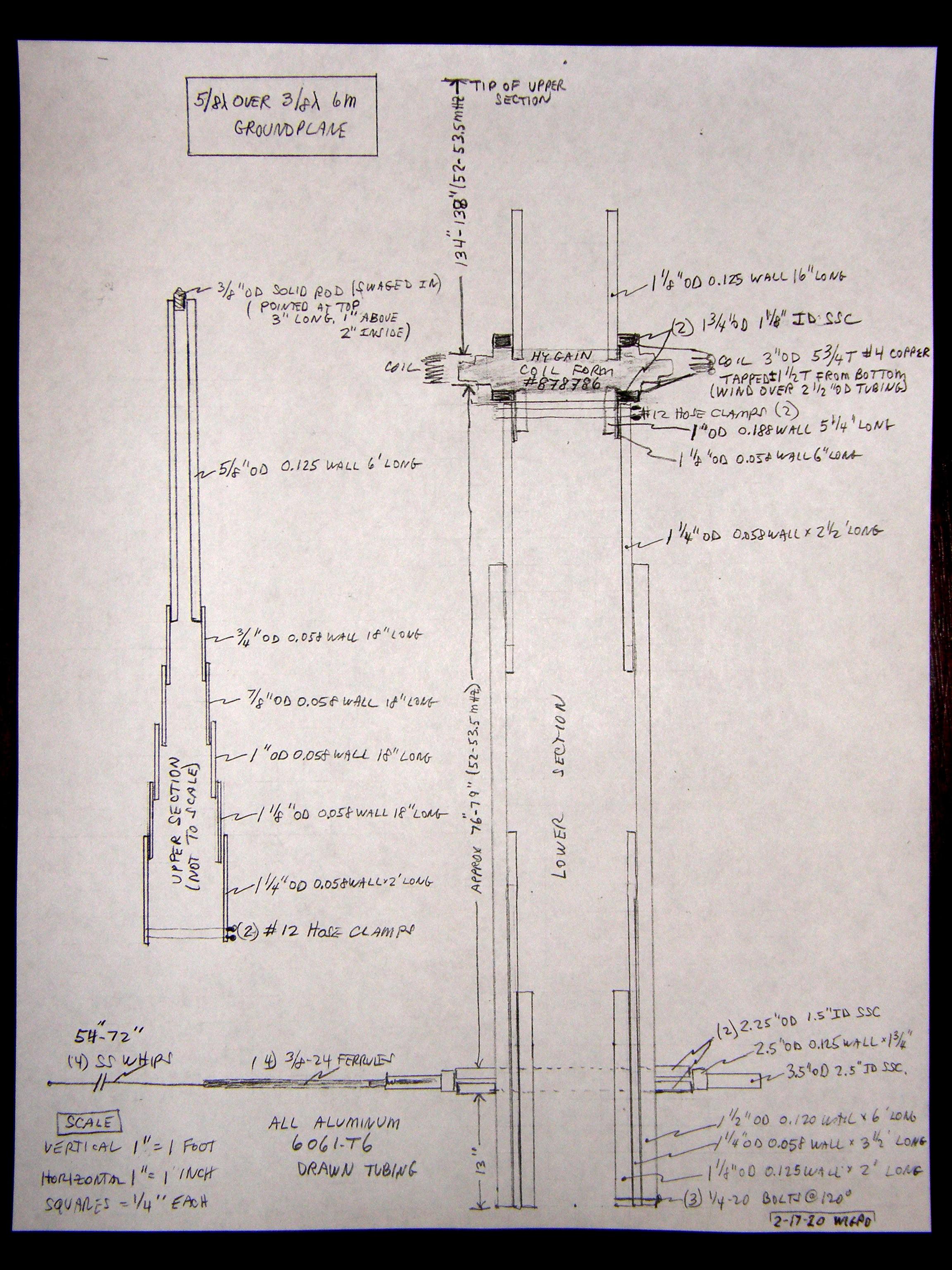
This antenna uses one set of horizontal radials, using just a coil form from Hy-Gain (MFJ). It should mimic a PD-315 in electrical performance. If you wish to make your own version of a V-6R, you might want to follow at least some of what we did in general with the following design. So far, if I was to do it over, I would have had the telescopic sections, at least above the coil, welded for better lightning resistance, although this design could be about as resistant as a commercial 1/4 wavelength monopole ground plane with solid 3/8 inch return, often used for top mounting on low band base stations where lightning is of concern. The just under 1/4 inch #4 solid soft copper has better conductivity than 6061 T6 aluminum, so it's possibly equivalent to 3/8 inch solid 6061. This version is shorter than the V-6R, so it has maybe 0.3 dB less gain at the horizon, but about the same gain as the PD-315, and a lot more, possibly 3 dB more, than the 1/4 wave ground plane with a lot more of the important capture area to reduce dead spots than the 1/4 wave ground plane with horizontal radials. Another improvement would have a machinist construct, from aluminum, a single whip hub to replace the three set screw collars and section of 2-1/2 inch OD tubing, and design it so it could be adjusted up and down unlike ours, which partially screwed into the 1-1/2 inch OD tubing.
Everything for this project was fabricated at home with just a drill press, taps, and typical household tools. It was not cheap (maybe $350) with almost half the cost in shipping and small quantities, and aluminum prices had gone up over the past year. Short leftover aluminum tubing can often be found on Ebay. DX engineering had the 1-1/2 inch OD, 0.120 wall tubing. Other suppliers included Get Metals and Online Metals. I purchased setscrew collars and loop terminals from McMaster-Carr. The #4 bare copper wire was obtained at Home Depot. Other local hardware stores supplied the hose clamps, etc.
The photo below is a detailed diagram of the antenna construction.
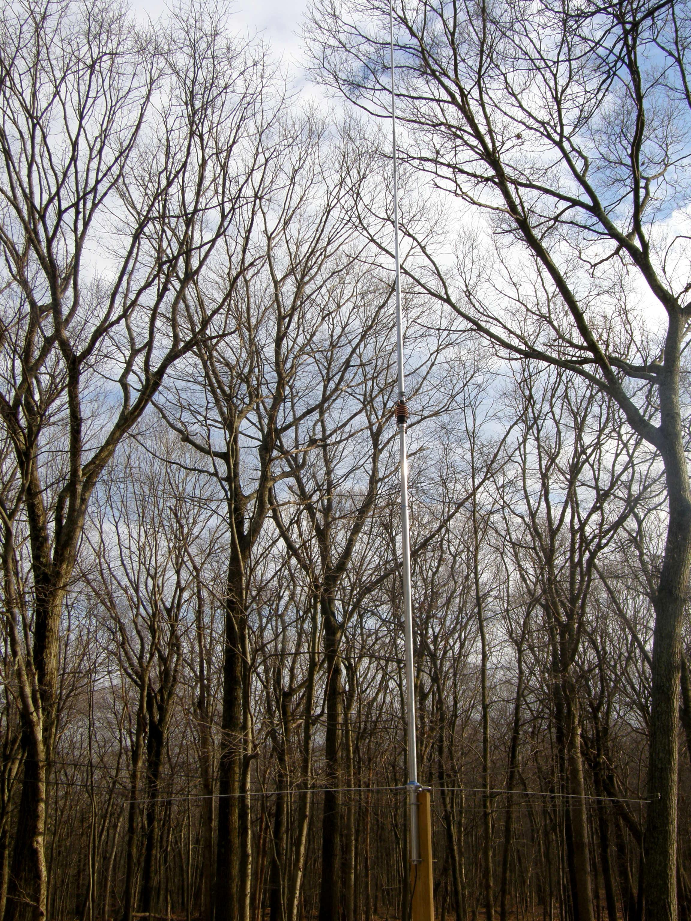
Here's a photo of the antenna mounted to a short mast on my porch.
Here are the major components of the antenna apart on a carpeted floor.
The setscrew collars from McMaster-Carr came with one black, probably not stainless, setscrew, which was replaced with a stainless setscrew from the local hardware store. Also, we drilled and tapped each setscrew collar for two additional #10-24 setscrews, to give three points of contact to where they fastened. #10-24 setscrews were used because they're easier to tap, and the threads are deeper than #10-32 and are probably better in soft aluminum.
The aluminum tubing appears to have equal flex along its length and guessing to be compatible with the shear strength of the coil assembly, judged by bouncing the assembled antenna horizontally above the floor with the radial assembly the only part touching the floor and thus becoming the fulcrum, with our foot pressing down on the bottom end of the antenna 13 inches below this radial hub. The top section of 5/8 inch OD tubing was made to be exposed over 5.5 feet so as to minimize top wind load and thus torque generated at the top of the antenna to the coil assembly by wind. It would have been great to have made it wider in diameter, or placed a 1-1/4 to 1-1/2 inch aluminum ball at the top like a Kreko heavy duty coaxial, to increase the SWR bandwidth beyond the 1.38 MHz 1.5:1 bandwidth with 1.03:1 SWR at center resonance the antenna measured at testing, but that is still better SWR bandwidth than a Kreko shunt fed co-plane. However, I do not think this antenna is physically as strong as a heavy duty Kreko co-plane, and might be half as resistant to a lightning hit? The pointed tip made from 3/8 inch OD 6061 T6, can easily have the top flattened and drilled and tapped to accept the #4 bolt from a Static Buster for Coronal Discharge reduction.
Coil:
The hole for the tap wire begins 2-1/4 inches down from the top of the cover, and slants upward at about 45 degrees to reduce water ingress. A Dremel tool can do this better without skipping out of the hole than could easily happen using a drill bit. To feed the jumper wire through the hole, it helps to solder a thinner flexible wire to it. The photo below shows the coil form before the new coil was attached.
The wire is wound around 2-1/2 inch OD tubing, and spread 1/4 inch between turns, with 3/16 inch air space to the outside of the Noryl coil cover. The coil should be 50-51 inches of wire before the wire is vertical to the ring connectors attached to the setscrew collars. Outside coil diameter is 3 inches. So somewhere in the middle of the bends, it should be 50 inches bend to bend. The tap point is adjustable by rotating these collars. We ended up about 1-1/2 turns from the bottom wire bend to vertical. If the antenna resistance at resonance is too low, LOWER the tap point, and visa versa, because the center of the coil should be near zero resistance, and we are feeding the lower element side of the coil with the coax, however, the very bottom of the coil is a short across the coax, so there is a sweet spot. Also, generally, the lower the tap point, the lower the resonant frequency of the antenna; another variable! See the completed coil photo below.
Coil ring connectors are for 1/4 inch hole and #4 wire. The ones from McMaster-Carr are for #6 stranded, which is still too big, so about 1/8 inch was cut away with a Dremel tool, so the connector could be bent tightly against the copper wire before soldering with tin-copper lead free solder (175W iron recommended).
UHF Barrel Assembly:
A 6 inch Teflon double UHF female barrel with gold plated center contacts proved to have less than 1.03:1 SWR at 6 meters so that should beat the original short UHF barrel with wax, and also allow for a much sturdier lower element connection. The two photos below show the assembly from each end.
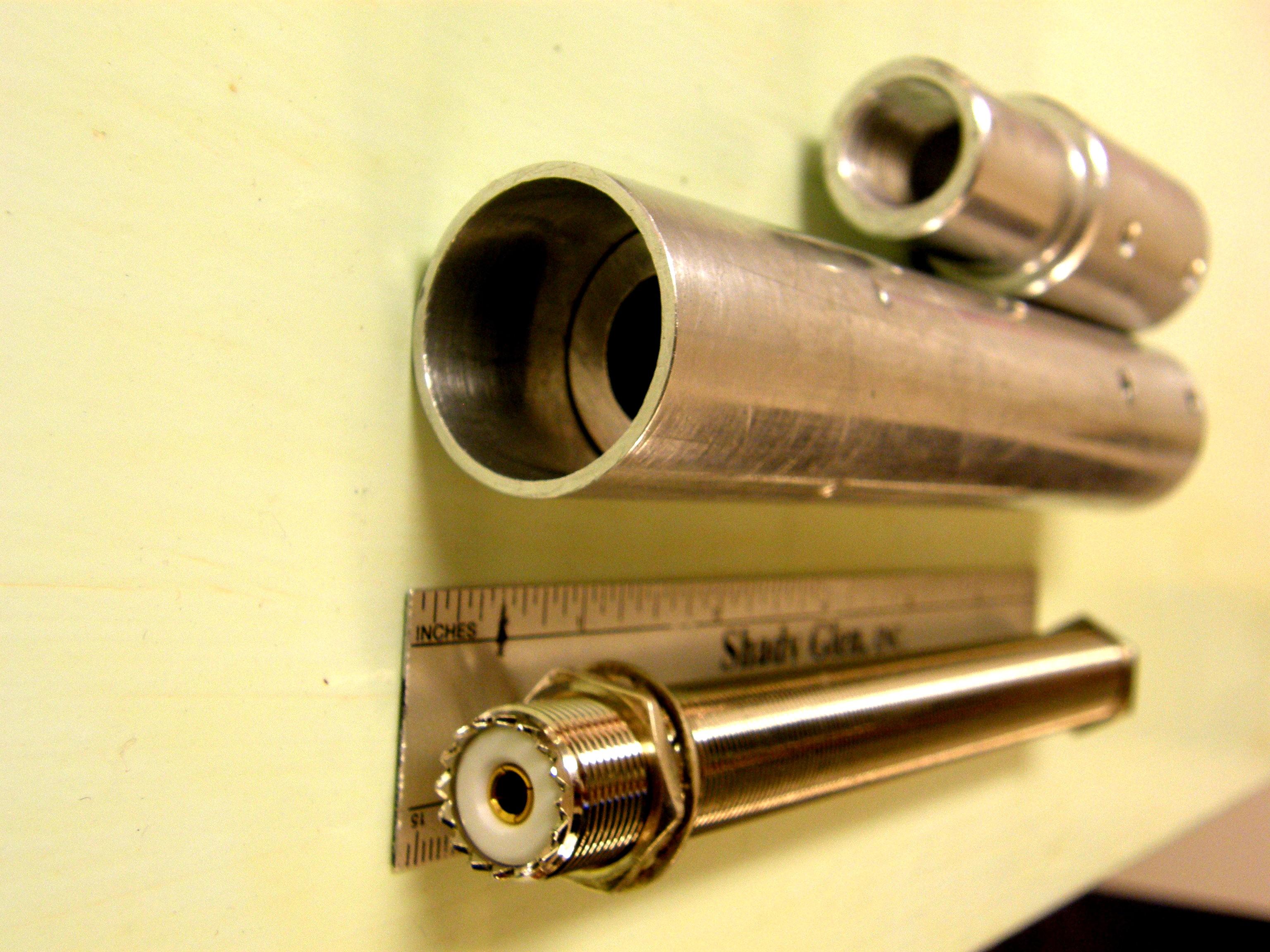
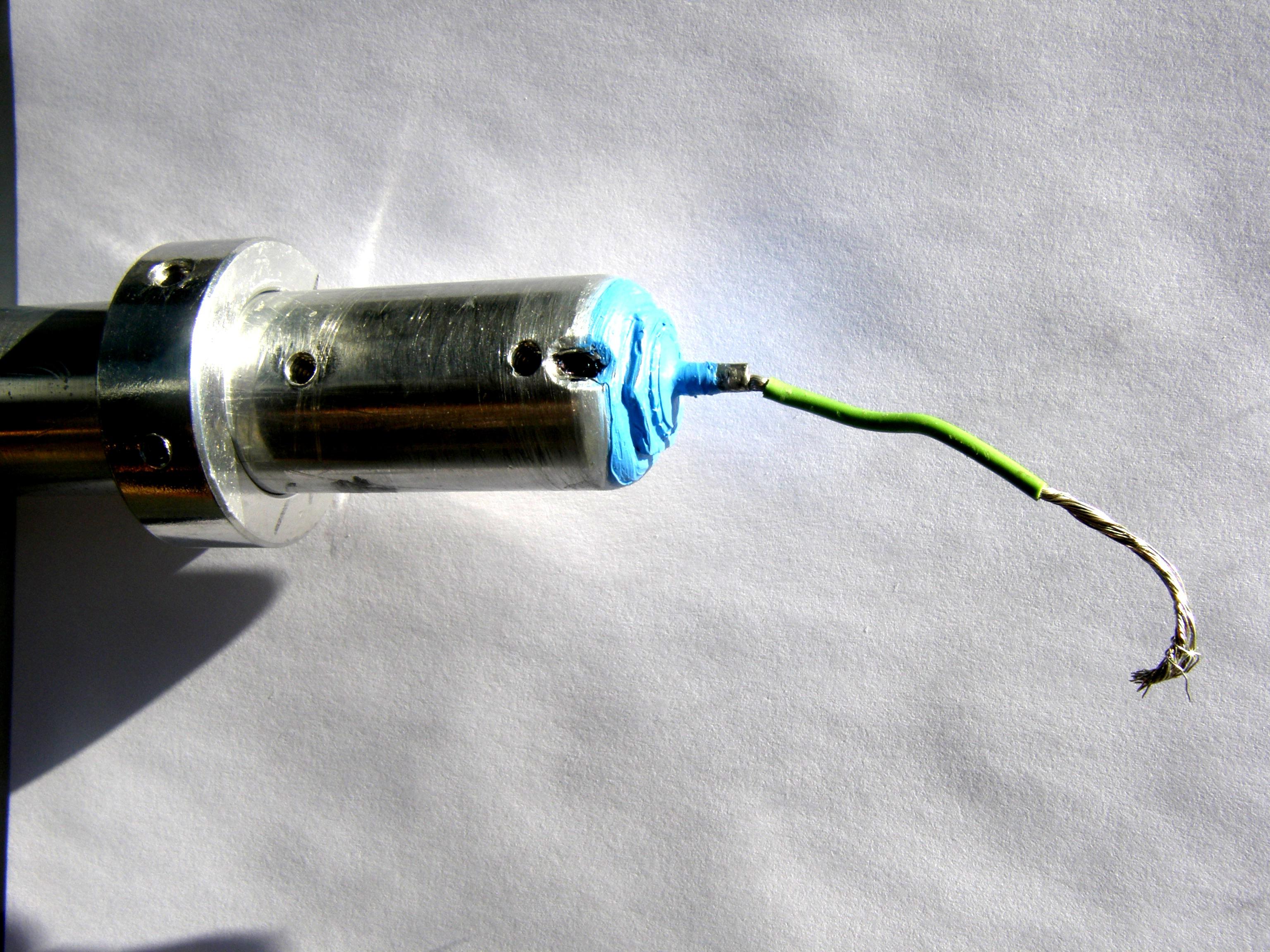
Note that 2 of the 4 circumferential indents shown were hammered into the outside of the 1-1/8 inch OD tubing near the antenna connector end to increase the snugness to the inner tubing. Also note that the end points were ground off the outer aspect of the 6 inch barrel at the wire end, to help the RF return flow back down to the lower element tubing.
In the photo below, note the drainage groove with the black mark at the top corner to allow water to drain from inside to outside at the bottom of the coil assembly. A MUST!
Radials:
The antenna was tested with 54 inch whips, but we plan to try 72 inch whip assemblies to see if the resonant frequency or antenna resistance changes, and try to test any performance change.
If the radials are kept horizontal, then extending them (for 52.5 MHz) from 56 to 70 inches (measured between the 1 1/2 inch OD tubing outside edge to the tip of the radial) should improve the groundplane a bit to produce a radiation pattern just like on the PD-315. We tried 72 inch whips (MFJ1964) that actually appeared to be excellent heavy duty quality, but the tips sagged down about 1 foot, so with ice bending them even lower, the antenna should detune lower in frequency the more they bend downward. As it turned out, just changing to 14 inch longer whips only lowered the resonant frequency of the antenna about 2 MHz, a lot less than if the whips were angled down below horizontal. To counteract the lowered resonant frequency, the length of the mast between the radials and the coil needs to be shortened perhaps 2-3 inches, or better yet, the coil shortened a couple of inches with a possible tap change. We decided to keep the original 56 inch whips. However, the ideal length (for 52.5 MHz) would have been 69 inch radials made of 3/4 + 5/8 inch OD 6061 tubing joined to the radial collar with 1/2 inch stainless threaded rod.
Update April 2020:
During a recent weather event, heavy snow on the exposed coil lowered the resonant frequency of the antenna by 0.5 MHz. It became apparent that a coil cover was needed, at least in repeater service. It was decided to use grey PVC electrical conduit. 3 inch Schedule 40 PVC has an inside diameter of 3 inches, and an outside diameter of almost 3-1/2 inches, so the end caps and coupling have an inside diameter slightly larger than this. The outside of the #4 gauge wire coil is 3 inches, so there's about 1/4 inch of clearance between the coil and the inside of the PVC coupling. A notch in one of the 3 inch conduit splices was required to clear part of the coil leads. See the photo below.
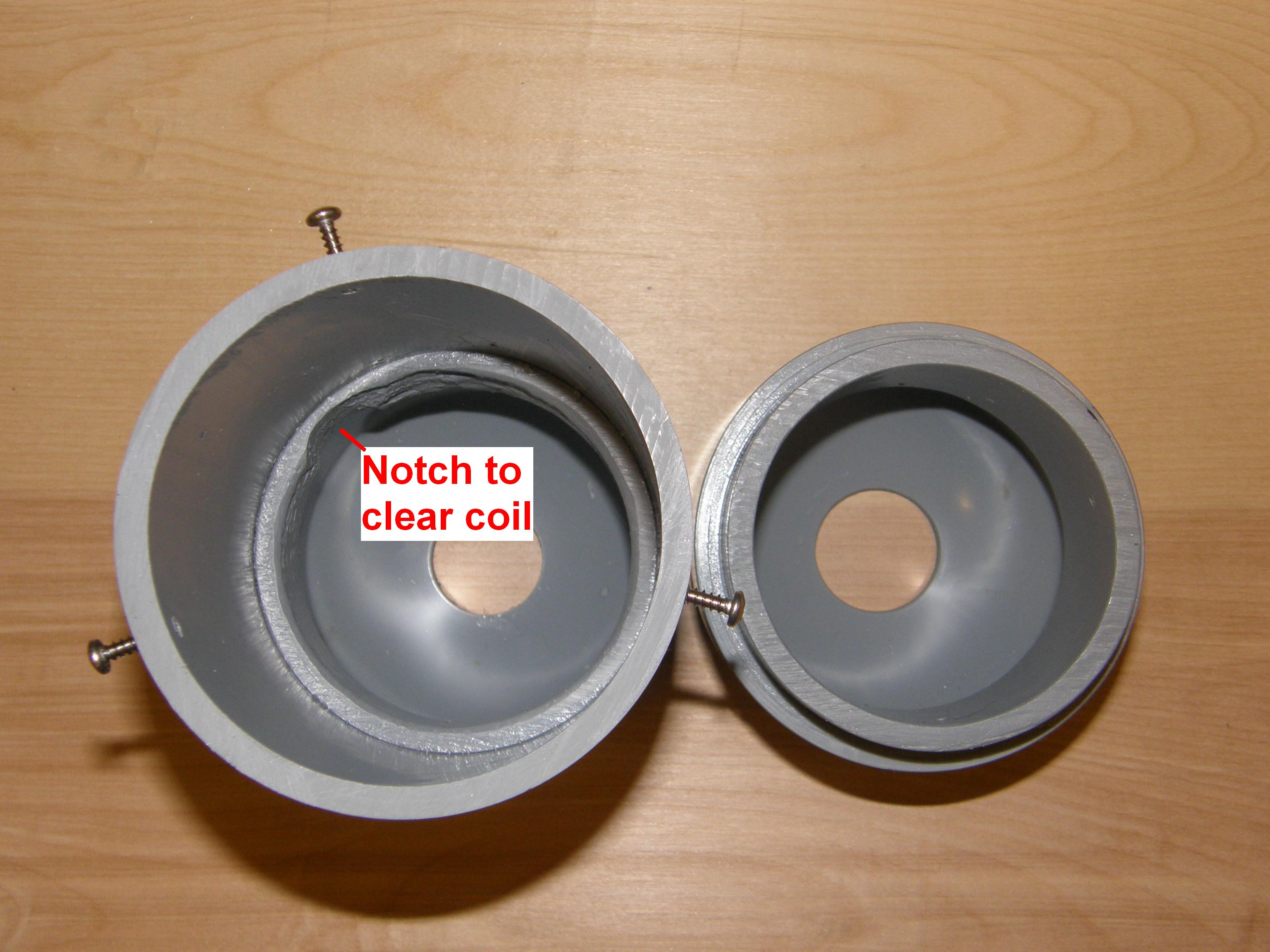
The housing is made from two 3 inch PVC end caps with holes drilled in the center of each one, a center section of a 4 inch long repair coupling for 3 inch conduit, and two cut sections about 2 inches long of 3 inch Schedule 40 to join the end caps and coupling together. A standard coupler has a ridge inside to prevent the pipes from being inserted too far; the repair coupler does not. The upper half of the bottom joint was joined by three screws instead of using the PVC cement that was used elsewhere, so the housing could be taken apart if needed for maintenance. The top 1-1/8 inch OD hole was sealed with Permaseal Ultra Blue RTV, and the 1-1/4 inch OD hole in the bottom end cap was left unsealed for any needed water drainage. See the photo below.
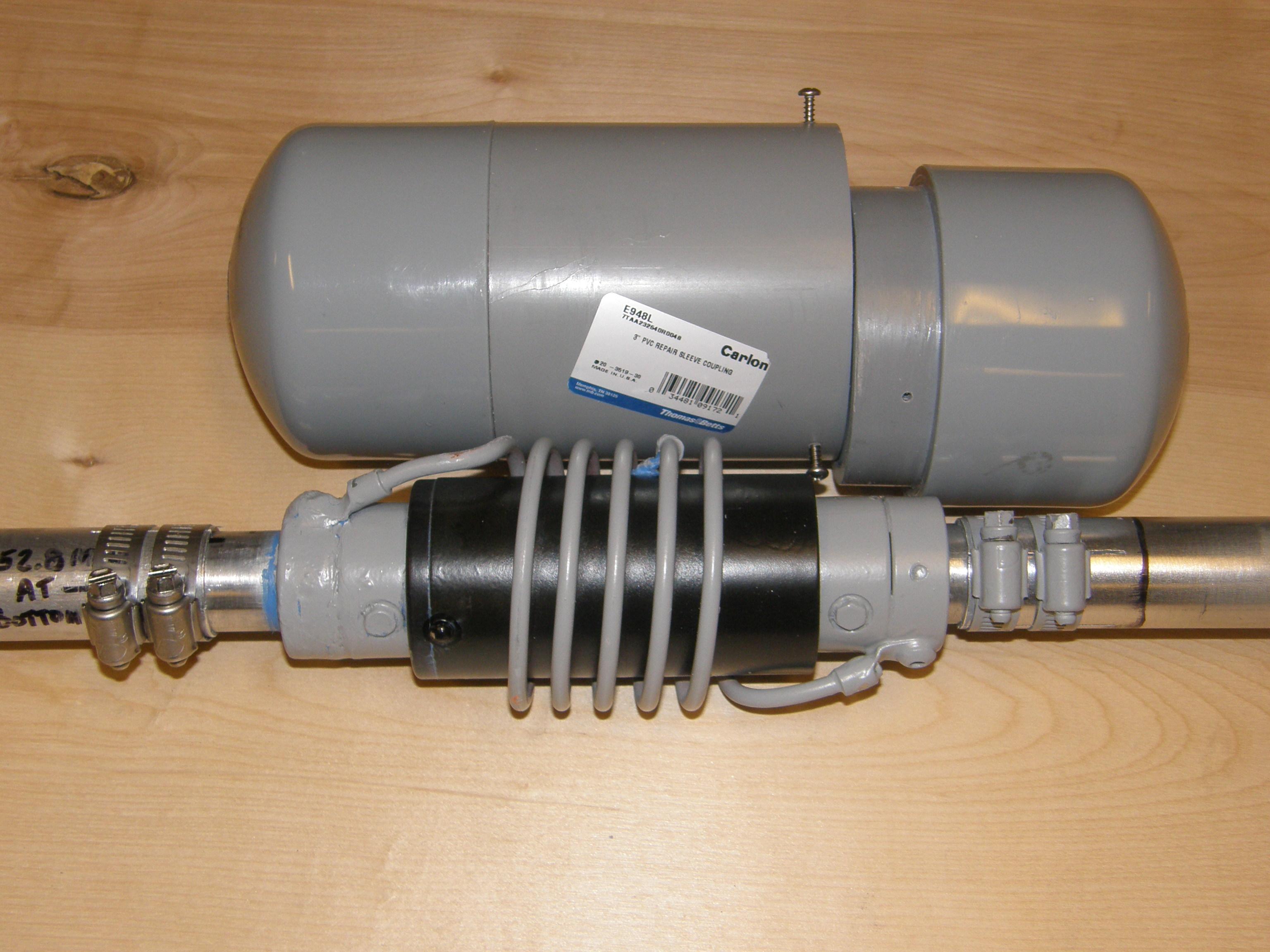
The coil was painted with grey primer some time ago, as an attempt to reduce detuning due to ice and snow, but that proved to be useless, hence the PVC cover. The conduit parts are UV resistant and rated for outdoor use, but are quite expensive (about $70!). Comparable white Schedule 40 3 inch PVC drain pipe parts would be MUCH cheaper, but the UV resistance is unknown. Here's a photo showing the complete closed coil cover.
This Is Still A Learning Experience:
First, John WB2CIK made an excellent suggestion from his experience with VERY high current behavior. He mentioned that a lightning strike of very high amperage through the coil will generate such a strong magnetic field that the stainless steel screws holding the bottom of the grey PVC electrical conduit cover up could be blown away! So these screws were changed to non-magnetic aluminum, as were two Hy Gain stainless fasteners anchoring the Hy Gain coil cover, which is now inside the new exposed #4 gauge copper replacement coil in the article. In addition, because of the magnetic kickback the coil itself will sustain, the 1/4-inch ring terminals are also epoxied to the set screw collars they are screwed in to.
Second, while the PVC electrical conduit generates zero heat in a microwave oven test, it still adds capacitance between the elements and around the coil, lowering the antenna resonant frequency, so with the addition of the PVC cover, about 3 inches of wire had to be removed from the top of the coil, and the tap adjusted closer to the bottom by a few inches. For 53 MHz, the 3-inch OD coil ended up with 5-1/5 turns with turns spaced from top to bottom 2-1/2 inch before the wires turn vertical. The tap ended up 1-1/4 turn from the bottom vertical position of the wire.
Third, if the temporary test mast is made of wood, then a wire more than 15 feet long needs to be dangled down to simulate a tower or metal mast. We used an extension cord clipped to the antenna base.
Recommended Tuning Procedure:
Because the active antenna is about 18 feet long, the antenna needs a lot of surrounding air space if it is going to me mounted in free space. Related to this is the so-called "inductive near field," which probably is about 15 feet, and the "reflective near field," which probably extends out another 39 feet, for 54 feet of total "elbow room"! This seems to compare well with our experience, but at a 40 foot horizontal distance there is barely a measurable SWR change. 15 feet is the bare minimum and probably too close, so it is a sliding scale. However, if the final location of the antenna is really going to be cramped, possibly tuning up at 15-20 feet to a horizontally positioned reflective material would be representative. The reason this is mentioned is the amount of "elbow room" probably influenced the position of the coil tap. The antenna height above ground at the test site is not as critical because there should be minimal down lobes to reflect back, but the radials should be at least 9 feet above a reflective surface, and 15 feet would be better. The more height the better except it makes adjustments a lot more difficult.
There are four interrelated adjustment variables: upper element length, lower element length, coil wire length, and coil tap position. The radials are always 56 inches. This means if you attempt to adjust this antenna just with an SWR bridge, you (me included) will get frustrated going around in circles! A methodical approach is required, and you need to be positioned at least 15 feet away and from the antenna and below the radials at least 6 feet any time you take a measurement.
Conclusions:
This article demonstrates that a background knowledge of the basic antenna principles (the ARRL Antenna Book is a good starter), a good antenna analyzer, and a willingness to spend the time improving or constructing an antenna, can bring very satisfying results.
Contact Information:
The author can be contacted at: jhaserick84 [ at ] comcast [ dot ] net.
Back to the top of the page
Back to Antenna Index page
Back to Home
This article created on Tuesday 18-Feb-2020
Article text and photographs © Copyright 2020 by John Haserick W1GPO.
Layout and conversion to HTML © Copyright 2020 by Robert W. Meister WA1MIK.
This web page, this web site, the information presented in and on its pages and in these modifications and conversions is © Copyrighted 1995 and (date of last update) by Kevin Custer W3KKC and multiple originating authors. All Rights Reserved, including that of paper and web publication elsewhere.