Antenna Index page
Heliax Notch Filter
By Robert W. Meister WA1MIK
and David W. Malicki N1OFJ

|
Home page Antenna Index page |
Constructing a Six Meter Heliax Notch Filter By Robert W. Meister WA1MIK and David W. Malicki N1OFJ |

|
Background:
All of this started a couple of years ago when an unused Telewave 45 MHz duplexer was discovered at a repeater site. Maybe we could get it to work on six meters. (The area needed another repeater like Jim Brady needed another hole in his head.) We tried retuning one cavity up to the 52-54 MHz range but the tuning rod stopped turning slightly below 51 MHz, so we abandoned the attempt.
There were several articles on the web about duplexers made from multiple quarter-wavelength pieces of Heliax coaxial cable; one is titled "6M Heliax Duplexer Design (Six Meter Duplexer) by WB5WPA"; search the web for "heliax duplexer" for further reading. It seems a handful of people have built these using various mechanical designs, but none had any explanation of how they calculated the length of the coax stubs. It was always "Use this handy calculator, then cut it to fit your application." Attempts to elicit more detailed information from the article's authors went unanswered, so we decided to investigate these filters ourselves and come up with the reasons why these were working and base our results on repeatable concepts.
Ultimately we want to put up a repeater on six meters. We have two antennas on the tower, but the repeater transmit signal was too strong and it completely wiped out any received signal. Rather than build an entire duplexer, we will try to build just the receiver half, which we figured must attenuate or notch out the transmitter signal by about 80dB. The rest of this article describes our designing, building, and testing efforts to make a series-resonant quarter-wavelength notch filter using 1-5/8 inch flexible coaxial cable and other commonly available components.
Please Note: We only built the receive half of what would be necessary for a full duplexer. The filter sections have never had more than a few milliwatts of power fed into them. One person reported that the tuning capacitor gets hot with 80 watts fed in, and I don't doubt it. The components are not rated for that kind of signal level and it was never our intention to use the filters described here on the transmitter's signal.
All Flexible Hardline Is Not The Same:
The first attempt duplicated the majority of the designs we saw on the web. We used a piece of all copper, air-dielectric, 1-5/8 inch Heliax and a piece of RG213 shoved inside the Heliax as a "gimmick" capacitor. It was easy to short out the bottom end of the coax simply by soldering the inner and outer conductors together. Unfortunately, this coax was too flexible and the center conductor was able to move around, thereby changing the tuning. The RG213 was too finicky, didn't make a good connection, and was very sensitive to mechanical vibration. While others may have had success with this setup, we didn't.
We were lucky to find several scrap lengths of 1-5/8 foam dielectric Cellflex LCF158-50JL coax. These had been cut off the ends of three cable runs at a new cell phone site. Each piece was 12-14 feet long but had been bent into a hairpin shape in the middle, probably to make sure it couldn't be used again. The pieces were also very muddy from lying on the ground. Each one cleaned up well. We can get two or possibly four usable quarter-wave pieces out of each one, so we're not wasting it. Specifications of this product were extracted from a web page and are reproduced in the table below.
| Parameter | Value |
|---|---|
| Cable Type | 1-5/8" Foam |
| Impedance | 50 ohms |
| Maximum Frequency | 2.75 GHz |
| VOP | 90% |
| Peak Power | 310 kW |
| DC Breakdown Voltage | 5.6 kV |
| DC Resistance (ctr/shld) | 0.396/0.205 ohms |
| Capacitance | 22.5 pF/ft. |
| Inductance | 0.056 uH/ft. |
| Outer Conductor | Aluminum (Corrugated) |
| Inner Conductor | Copper (Corrugated) |
| Diameter Over Jacket | 1.98 in. |
| Min. Bending Radius | 20 in. |
| Bending Moment | 34 ft-lbs |
| Weight Per Foot | 0.78 lb/ft. |
| Tensile Strength | 405 lbs. |
| Atten/100 @ 30 MHz | 0.116 dB |
| Atten/100 @ 50 MHz | 0.151 dB |
| Avg Power @ 30 MHz | 30.8 kW |
| Avg Power @ 50 MHz | 23.7 kW |
Further parameters were obtained from a Cellflex Lite sales brochure, shown below.
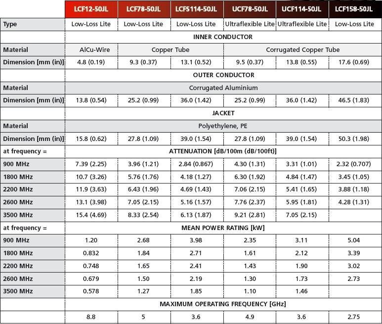
What we didn't realize until we stripped it back, (we didn't know the part number when we obtained the pieces) was that this particular coax had an aluminum outer conductor and a copper inner conductor. It's nearly impossible to solder anything to aluminum without special flux and solder, which I did find but haven't tried using yet. Ordinary electronic tin/lead solder sticks great to the copper, but balls up and rolls off the aluminum. So we could not make a good electrical connection due to the dis-similar metals (aluminum and copper). This may be an issue in the future as the contact points build up oxidation. As you will discover shortly, we made a good mechanical connection but this too may not last forever. It has been recommended, by someone experienced with this problem, that we utilize some conductive grease between the copper and aluminum. More information is presented at the end of this article.
Eventually we found a schematic of a Heliax duplexer that someone had designed, complete with actual component values. (Note that this was very close to the frequencies we were using, but it is not what we ended up building.) We determined that the piece of RG213 was actually a tuning capacitor with a value around 7pF. Dave discovered the piston trimmers at Hamtronics and they proved to be ideal for this project. See the schematic below. This image is used by permission from Jim Poll, WB5WPA.
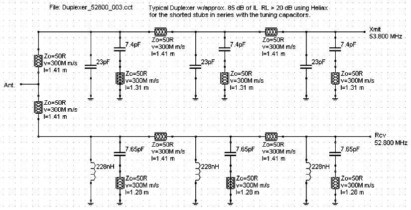
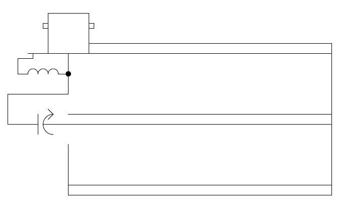
Each section becomes a series-resonant LC notch filter with the coax cable stub acting as the inductor. The input and output connections are made with one connector on the coax and a TEE adapter attached to that. Many of the designs on the web use two connectors and do away with the TEE adapter. Either method should work fine, but Dave found a bag of free BNC TEE adapters and it was cheaper to use them than buy additional BNC jacks. A peaking coil is added across the entire filter to improve the pass-band loss BELOW the notch frequency, or a capacitor is added across the connector to improve the pass-band loss ABOVE the notch frequency. In our case, we need to reduce the transmit signal at the receiver, so we're notching 53.75 MHz and passing 52.75 MHz. Multiple sections can be connected in series using 36 inch lengths of RG58. We're hoping for an improvement in notch depth when we attach more sections, i.e. the actual depth could be greater than the sum of the individual notch depths, something that often happens with multiple section filters. Unfortunately the pass-band loss also increases, but on six meters it may not be that important.
Calculating the Coax Length:
The standard formula for one electrical wavelength = 300,000,000 / F (Hz). Take 1/4 of this for the quarter-wave stub. Multiply by the Velocity Factor (VF) to get the mechanical length. We needed receiver cavities to reject 53.75 MHz and pass 52.75 MHz.
                            300,000,000 meters/second
one electrical wavelength = -------------------------
                             53,750,000 cycles/second
one mechanical wavelength = one electrical wavelength * VF
At our notch frequency (53.75 MHz) this reduces to 300/53.75 = 5.581 meters. At 39.37 inches/meter, the wavelength is 219.7 inches. Divide this by four for the quarter wave piece and we now have about 55 inches. Multiply by the published Velocity Factor (Velocity of Propagation, or VOP) for this foam dielectric cable (0.9) and we get about 49.4 inches for the mechanical (physical) length.
So we cut a piece 52 inches long, fully expecting it to resonate a bit lower than 53.75 MHz, and prepared it as described in this article. Unfortunately, a piece of coax this long with a 10pF series capacitor resonated around 46 MHz, so we started shortening it by inserting dry-wall screws through the coax at different points. We got a decent dip at 53.75 MHz when we got all the way down to 41 inches long. This means the actual Velocity Factor for the coax we used was 41 / 55 = 0.74, far from what has been published. It is not known why this was so far off.
Material Required:
| Part | Source | P/N | Description | Qty | Price |
|---|---|---|---|---|---|
| BNC Jack | Jameco | 174290 | BNC female chassis mount | 1 | $1.85 |
| Screws | Anywhere | Any | #6-32 x 1/4 pan-head | 2 | $0.00 |
| Trim Cap | Hamtronics | A49 | 1-11pF piston trimmer | 1 | $2.00 |
| Red Coil | Hamtronics | A96 | 2-1/2 turn (red) slug-tuned coil (65nH) | 1 | $3.00 |
| Hose Clamp | Home Depot | Size 36 | Stainless to fit 2 inch hose | 1 | $1.30 |
| Coax Cable | Anywhere | Any | 1-5/8 inch 50 ohm foam | ~4ft | $0.00 |
| BNC TEE | Jameco | 658515 | BNC F-M-F adapter | 1 | $2.15 |
Note that the Hamtronics parts are in quantities of 5 or 6. Since we'll be making at least three filter sections and possibly four, this worked out well for us.
At my request, my brother measured the red and blue Hamtronics coils with his HP 4262A LCR meter: the red coils were 60-90nH (nominally 65nH), the blue coils were 180-330nH (nominally 220nH). We've tuned the red coils for maximum inductance, and they could use a bit more.
Detailed Component Description and Notes:
BNC jack: female, 50 ohm, 4-hole chassis mount. This one was tin-plated and had pre-tapped holes for #2 or #3 screws.
Coaxial cable: we found several 10-ft lengths of fresh Cellflex LCF158-50JL that were cut off the ends of longer runs at a cell phone tower installation. This particular product has a thick black polyethylene outer insulation, a thick aluminum outer conductor, and a thin spiral copper inner conductor with foam insulation glued to it.
There were two styles of 2-1/2 inch hose clamp at my local Home Depot, both in the same box. One had a lot more screw threads in the strap and would obviously handle a bigger hose size variation; it is stamped "2-3/4 Size 36" and says "19-70mm". I suspect that the other clamp might have a range of around 40-70mm (maybe it was truly a 1-3/4 to 2-1/2 inch clamp) which could run out of adjustment range when used on this coax.
I learned something about worm-drive hose clamps. The size value is an SAE (Society of Automotive Engineers) standard. Take the nominal diameter and multiply it by 16 to get the SAE Size value, or divide the SAE Size value by 16 to get the diameter in sixteenths of an inch. In this case, Size 36 means the nominal diameter is 36/16 (2-4/16, or 2-1/4) inches. This doesn't say what the minimum or maximum diameters are, unfortunately.
If you can find all-copper coax cable, you can do without the hose clamp and try soldering the folded inner conductor to the outside of the outer conductor. Ours was aluminum and we were unable to solder the copper to it with ordinary electronic (60/40 tin/lead) solder.
The BNC TEE adapter isn't really part of the filter, but since we used only one BNC connector and the filter has to have an input and an output, the TEE is necessary to hook it up. You could use two BNC connectors and join the center contacts, hooking the tuning components to that spot; you could then eliminate the TEE adapter.
Component Preparation:
BNC jack: drill two adjacent holes 1/8-inch diameter and tap for #6-32 screw. File off burrs. Scrape or file some tin coating off the back so solder will adhere to it. If there's an indentation or "cup" in the center conductor of the connector, choose the two opposite holes, so when you mount the connector, the "cup" faces upward. Technically, you should use a #35 or #36 drill (7/64 or 0.110 inches) for a #6-32 tap, but the 1/8-inch drill (0.125 inches) works fine. Also, you could drill larger holes and use #6-32 nuts behind the connector rather than tapping it.
Capacitor: bend the long (upper) terminal outward to about a 45-degree angle.
Inductor: bend the leads to fit across the BNC connector.
Hose clamp: preset for about 2-1/2 inches in diameter.
Cable Preparation: Bottom End:
"Measure twice, cut once." That really applies here. As my barber always reminds me, you can cut it shorter but you can't make it longer.
I used my 14-inch woodworking band saw with a 10tpi (fine-tooth) blade. It cut through the aluminum and copper coax like a knife through a loaf of bread. I used a miter gauge to insure perfect right-angle cuts and a stop block to prevent cutting into the center conductor. A hacksaw will also do the job just fine but it will take a bit longer. The dimension tolerance is 1/4 inch. Nothing is really critical. If you're concerned, make them bigger and cut off any excess center conductor after you've prepared the bottom end.
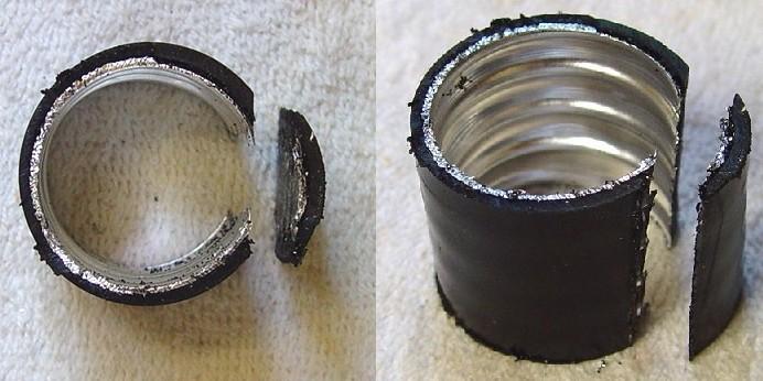
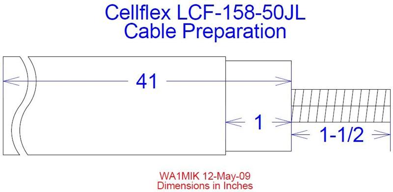
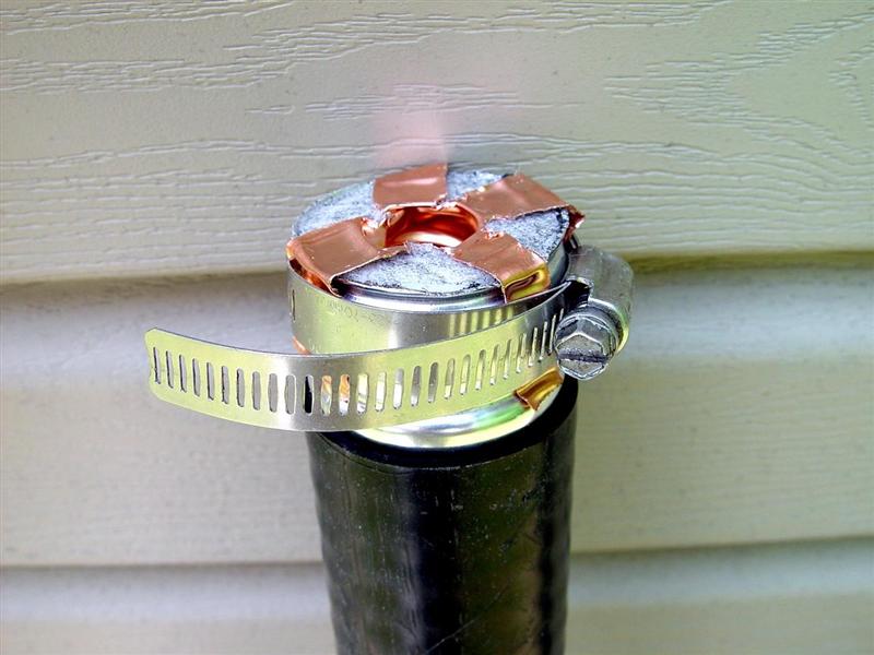
All of the bottom-end work took me about half an hour to accomplish, including photos.
Cable Preparation: Top End:
The top end requires a lot more trial-and-error. There are a lot of little things to do. Most can be accomplished with a sharp utility knife or standard size diagonal cutters.
We decided to make each cavity with one BNC female connector and use external TEE adapters. The procedure below was written for this configuration. You can also use two connectors and eliminate the need for the TEE. You'll have to duplicate most of the procedures for the second connector, and the orientation and placement of the piston trimmer capacitor and coil will be different. Connect the center terminals of the two BNC connectors together and treat that as one point. Connect the other components to the center of that connection.
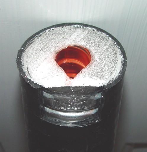
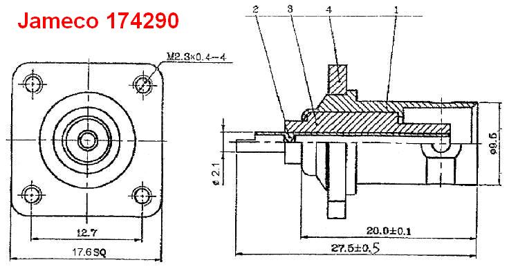

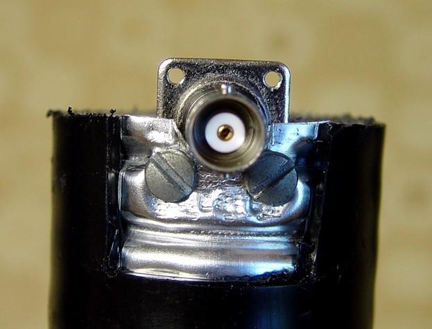
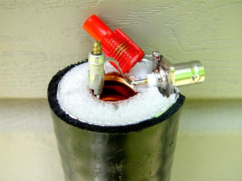
These three components are mechanically very stable when mounted as described above. I didn't have to shorten any leads; they were all just long enough. With a lot of running between my workbench on the second floor and the tools in the basement, the top end took me another half hour to complete, including photos.
Some designs enclose the entire top end in a metal box, mounting the connectors to the box rather than the coax. This affords some shielding and helps keep unwanted critters and curious fingers out.
Tuning:
The first section we made had an N-female connector on it, but this was only because we hadn't bought the BNC connectors yet. Also, the inductor across the connector had not been added initially as we just wanted to experiment with the series-tuned capacitor and coax. A TEE connector was attached to the filter and this was connected to a spectrum analyzer and tracking generator. We merely adjusted the piston trimmer for a minimum (dip) at 53.75 MHz; you should get close to 20dB notch. The response curve was very well centered and had equal loss at 52.75 and 54.75 MHz, about 1-2dB.
The inductor was added to reduce the pass-band loss at 52.75 MHz. We tried a blue coil first (6-1/2 turns) but that did nothing at 52.75 MHz. The red coil (2-1/2 turns) worked much better. The tuning core was adjusted to minimize this loss. I used a round wooden toothpick that I shaved down to fit the square hole in the coil's tuning core. You may wish to purchase the proper tuning tool from Hamtronics when you order the coils and capacitors. This inductor performed nicely but we may experiment with hand-winding our own coil to give us less loss at 1 MHz below the notch frequency. If you are using other than 1 MHz spacing you'll probably need a different coil as well. If your pass-band frequency is above the notch frequency, the coil would be replaced with a capacitor. Here's a generic schematic of one section where the pass-band frequency 1 MHz below the notch frequency:
Results:
Our prototype and first working notch filter had about 19dB rejection at 53.75 MHz and 1.6dB pass-band loss at +/- 1 MHz.
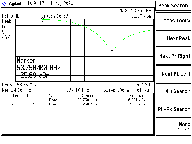
After adding the peaking coil, cutting the coax to 41 inches, and installing a BNC connector, we ended up with over 25dB rejection at 53.75 MHz and under 0.4dB pass-band loss at 52.75 MHz. Here's the peak and notch response on the spectrum analyzer:
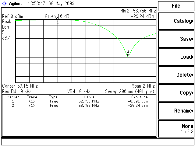
The second filter had even better performance, with over 29dB rejection at 53.75 MHz and under 0.4dB pass-band loss at 52.75 MHz. The tuning capacitor was nearly at the bottom of its range however, even though the manufacturing techniques were identical. I didn't even have to tune the peaking coil; it was right on. Here's the peak and notch response on the spectrum analyzer:
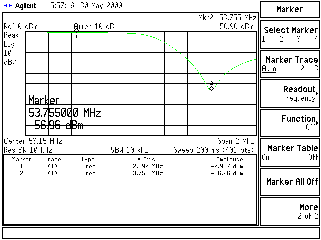
We then combined these two sections using a 36-inch piece of RG-58. We were hoping that the two filters would give better results than the sum of the individual filters. They didn't, but we did get decent results. We had to slightly tweak all the tuning components after connecting them together, but it was easy to do. The notch depth got up to 57dB and the pass-band loss was just under 1dB for two sections. The results of two filters in series, is shown below. Note that the best pass-band loss was just slightly below 52.75 MHz.
Dave built a third section by following the instructions in this article. He made his 41-1/2 inches long. From what we could tell, this extra length did not affect the tuning or the performance. We still got about 0.45dB passband loss at 52.75 MHz and 26.5dB notch depth, right in line with the other two sections.
This table summarizes the performance we got as we joined sections together.
| Sections | Pass-band | Reject |
|---|---|---|
| 1 | 0.4-0.5dB | 25-30dB |
| 2 | 0.9-1.0dB | 55-60dB |
| 3 | 1.3-1.4dB | 80-90dB |
| 4 | 1.9-2.0dB | 100-105dB |
| 4 (final) | 2.25dB | >110dB |
The second filter seemed to be just a bit shorter than we needed it to be. The third filter was made 41-1/2 inches long to lower its effective frequency range, thus requiring a bit less capacitance to bring the notch where we want it.
As with the first two sections, we had to retune the entire string when we added the third section. We also found that holding the sections near the top had an effect on the tuning. If we had enclosed the top end of the filter, this effect would have been eliminated, but it would have greatly increased the manufacturing effort. Placing the sections next to each other had an effect on the tuning as well.
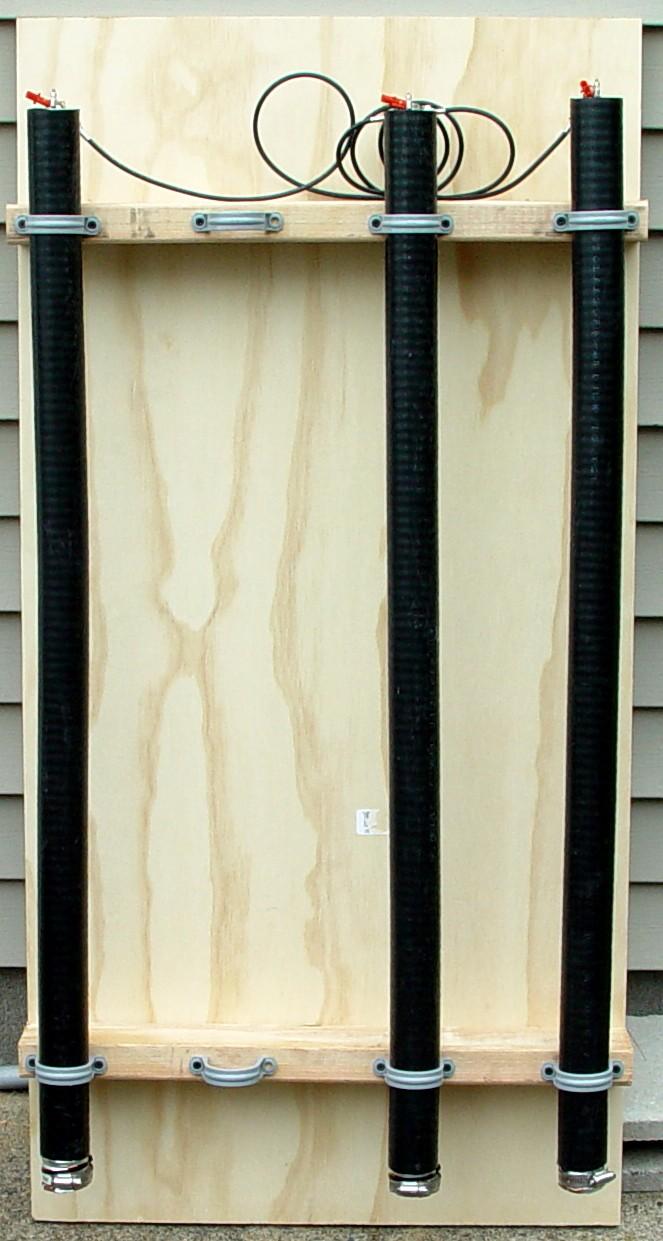
Our final step will be to clamp these three sections to a piece of 3/4 inch plywood, 2 ft by 4 ft, separated by about seven inches, elevated by two pieces of 2x4. When the entire filter assembly is installed at the site, we will retune it once more. See the photo below. (No, we didn't screw up; the extra space is for a fourth section we plan to add later.)
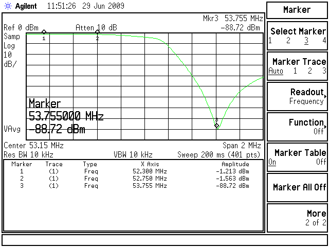
Here's a spectrum analyzer trace of the three-section filter. Marker 1 is the point of maximum signal (minimum pass-band attenuation of about 1.2dB) and is considerably lower than the intended pass-band frequency. (We think that new peaking coils can bring this point closer to where we want it.) Marker 2 is at the intended pass-band frequency of 52.75 MHz and it shows just about 1.5dB of insertion loss. Marker 3 is at the intended notch frequency of 53.75 MHz and it shows 88-90dB of rejection loss.
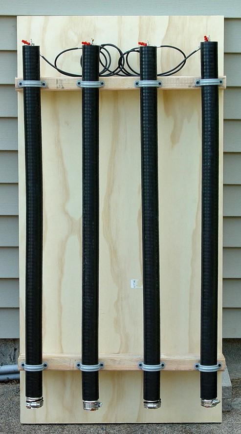
A fourth section was made, tuned up, and added to the other three sections. Even though this new filter was cut a bit long, it would not tune with the 1-10pF capacitor. I ended up adding a 5pF disc capacitor across the variable capacitor, and it tuned right up and gave me about 26dB rejection. Here's the completed four-section filter:
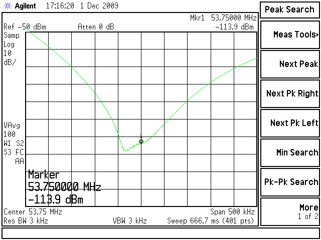
After retuning the entire filter as one assembly, I checked the tuning of each individual section. Two were dead on with maximum null at 53.75 MHz, one was slightly high, and the last was slightly low. I retuned those last two then measured the notch spectrum one more time, shown below. The unit had been in my garage overnight and the temperature was around 40F. I will pull it inside and check the tuning again to see what drifts after it warms up.
Problems with Dis-similar Metals:
Kevin W3KKC submitted this information. I thought it was important enough to add in its entirety.
I have extensive experience with this type of coax construction as I have used it for years in duplex service. I can tell you that if you don't protect the mating surfaces, eventually they will fail. I have used copper interfaces with aluminum sheathed CATV coax to convert the 75 ohm cable to a 50 ohm source/load. The mating of these metals can be drastically improved and service life extended by using common conductive grease like used in the electrical field. Products such as Nooxid, Noalox, NoCorrode, and Penatrox, are some brand names of this grease. It is important not to haphazardly apply the grease, but rather apply a conservative amount to the metals only and insure that none of it touches the foam insulation (remember, it's conductive). The result of NOT using it, after time, would surely be a good intermod generator.
Acknowledgements and Credits:
Jim Poll's original article can be found here.Heliax is a trademark of Andrew Corporation, now owned by CommScope Inc.
Cellflex and LCF158-50JL are trademarks of Radio Frequency Systems, Inc.
Nooxid, Noalox, NoCorrode, and Penatrox are trademarks of their respetive companies.
Help and suggestions from Mike K5JMP were gladly accepted and appreciated.
Thanks to Jim K2WU for measuring the Hamtronics coil inductances.
Thanks to Kevin W3KKC for the suggestion about the conductive grease.
Contact Information:
Bob can be contacted at: his-callsign [ at ] comcast [ dot ] net.
Dave can be contacted at: his-callsign [ at ] hotmail [ dot ] com.
Back to the top of the page
Back to Home
Back to Antenna Index page
This page originally posted on Saturday 30-May-2009
Article text, artistic layout, photographs, diagrams, and hand-coded HTML © Copyright 2009 by Robert W. Meister WA1MIK unless otherwise indicated.
This web page, this web site, the information presented in and on its pages and in these modifications and conversions is © Copyrighted 1995 and (date of last update) by Kevin Custer W3KKC and multiple originating authors. All Rights Reserved, including that of paper and web publication elsewhere.