Introduction
Due to the inability of certain people to communicate properly and understand all the aspects of site testing this page was created to read, compare notes and build on for the benefit of all. Human communication, comprehension and understanding problems is beyond the scope of this document, however the reader should keep these problems in mind when dealing with site issues and interfacing with other companies and government Agencies. Misunderstandings, bogus readings, log entries, technician and management diagnostics and plan of actions for problem solving are commonly mis-directed with considerable time and expense wasted in the wrong direction of efforts. This can lead to the general desensitation (pun intended) and poor attitude of the workforce in most any private company or government in the technical (repair) field around this country. Fortunately, there still is a handful of technicians that care to understand what the problem is and the proper way to solve, or at least, reduce the symptoms to an acceptable figure. If you are reading this it's most like you are in one of the latter. This is a good thing.
While past 2-way industry uses the "watts" figure, competent companies, such as Motorola provide supplemental training to LMR technicians in better practices and methods to perform their jobs, by forgetting the "watts" and "volts" figures and work with logarithmic figures instead. This philosophy will be realized in this entire document. One other note that this document has antenna gain (and some other types) figures are sometimes rounded off to the nearest dB for ease of calculations for readers only for educational reasons. Obviously, real field figures could have fractional amounts.
The author has been using the procedures/tests here, since 1978, both professionally and non-professionally. The latter is for Amateur radio where repeater owners try to get the best possible performance out of a station. These procedures can be used for any LMR type of service. These are for a standard, stand-alone VHF repeater, closed spaced between the transmitter (output) and receiver (input) frequencies. Keep in mind the transmitter is running in the neighborhood of +50 dBm, while it's receiver is trying to listen to a signal in the neighborhood of -117 dBm, while on the same antenna. (167 dB difference). While other bands (6, 1 1/4, .7 meter, etc.) theory is the same; most Amateur repeater owners have problems on the 2-meter band, therefore, the examples will be focused on that. The Motorola Quantar base/repeater unit will be the prime example for equipment covered in this article, however this practice can apply to any 2-way brand and model of equipment. The Quantar Tx power out is rated at +50 dBm, so if your station is difference take that into consideration when evaluating performance.
Procedures
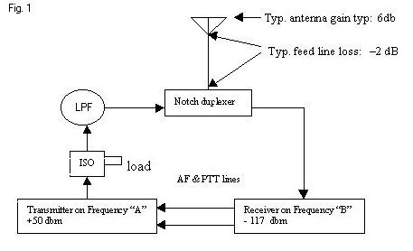
Figure 1 shows a basic station. Normally you'd have a transmitter-receiver unit, typically in the same chassis, with (proper length) cables connecting to a 3-port device, called a duplexer; with the common port connected to the antenna. Shown here is a basic band-reject for this study. More commonly are band/reject type duplexers used, for the advantage of additional filtering outside the repeater's frequencies and normally a slight increase in insertion losses, however, gaining in system performance. Since the price tag is still manageable for the latter type, it's recommend to use this type for all sites with other stations nearby.
Typical feed line loss is 2 dB, while the typical antennas used today are around 6 dB gain. Also shown is the optional isolator, with it's associated low pass filter. This filter is mandatory for proper isolator operation, especially if there are other stations at the site. For the Motorola Quantar having a single stage isolator built-in the unit, it's unknown (at this time) if there's also a LPF built-in as well. If not, second harmonics can penetrate the isolator and do more harm than good.
Perhaps some basic theory on the isolator is in order. This device normally is tuned in two directions, forward and reversed (reflected) on the same transmitter's frequency. RF power will easily run through the device in the direction of the antenna, while RF in the reverse direction is re-routed to the 3rd port, with a termination. The circular arrow indicates this, hence a "circulator". With the addition of the termination on the 3rd port the device now carries this name. It's almost semantics, between "isolator" and "circulator". While looking at the path from the antenna to the termination it's important it will handle enough power anticipated, including the station's own transmitter, in the case of a broken antenna, thus a bad return loss figure. (Reflected power coming back from the line/ant fault) This can protect the transmitter.
Occasionally, another scenario happens. If a nearby adjacent transmitter's power is coming down the line, so close in frequency any bandpass cavity won't filter it out, the reverse direction of the isolator can be tuned to that neighbor's frequency (instead of your own transmitter's frequency) to route that (offending) power to the termination as well. The drawback is that your own transmitter may not be protected. To overcome this you can install two isolators; one on each frequency.
In either case, routing return loss to the termination greatly reduces the chance of an IM mix in your station transmitter output section, the power amplifier. Power amplifiers for 2-way F.M. is usually type class C, which is a opportune mixing point for two or more signals to produce "other" unwanted (interfering) signals.
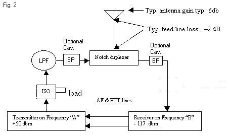
The Motorola Quantar base receiver is "stagger" tuned in the RF front end, from the factory. This is to accommodate a multi-frequency base station. Sometimes, single frequency increase in performance can be realized if the front end is retuned for a single RF peak. This may also help in adjacent channel degradation from other stations at the site. In some cases, where a site is "hostile" (in RF terms) a bandpass cavity can be added on the receive side to further enhance filtering as shown in figure 2. This of course, does not come without a price, usually in the form of 1-3 dB receiver (insertion) loss of sensitivity. However, if this cavity improves the over-all performance by filtering out adjacent signals, then it's a system gain in performance. (reduction in desense minus I.L.= increase in system performance).
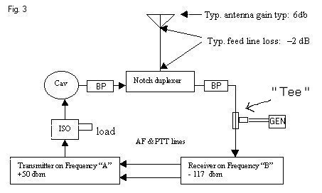
To test the system performance (repeater and/or base station's sensitivity) you can perform the following tests as (partially) shown in figure 3. Two test are involved, one, site (noise) degradation, and, two, repeater degradation (Tx-Rx). Both tests check desense of the station's receiver. Each test must be performed separately to properly evaluate and document the station's performance and find possible solutions to a problem.
This cannot be stressed enough.
First, connect any good quality signal generator in line with the station with an "iso-tee". This device has a through put, plus an isolated third port. The reason is not to load, or affect the line impedance or other variables, plus to protect the signal generator from the high powers of the transmitter(s). True, a quick "spray" method can be used, by a little whip antenna on the signal generator, however this induces propagation variables and should be only used as a last resort, or a rough measurement. For this exercise we do not recognized this "spray" method. Continuing, the "safest" point to install this device is on the receiver side, to prevent a mixing variable with high power levels as in the case of a site sharded with broadcast stations.
Test # 1: SITE NOISE
Step 1: Connect an "Iso-T" in the receiver line, with the third port connected to the RF signal generator.
Step: 2: Terminate the antenna port of the duplexer with a load.
Step 3: Measure and log the signal generator level to produce a receiver indication.
NOTE: This can be squelch break point, 20 dB quieting, or 12 dB sinad. Any method is satisfactory, however, the same method must be used for the entire test(s) to be accurate. There will be considerable isolation with the "T", so your signal general levels will be rather high, typically -50 dBm. The absolute level you'll need to do this is not important. What is important is the relative change in signal general levels (in dBm) that you will be logging in the next steps.
Step 4: Connect the antenna port of the duplexer to the outside antenna.
Step: 5: If there is a change in the receiver, adjust the signal generator level to produce the same receiver same indication as discussed, above. This normally will be an increase in the generator level. Log this measurement.
Step 6: The difference between the generator levels in step 3 and 5 is your site noise, or site receiver degradation in the from of desense. O would be great; typical is 4 dB.
NOTE: Some telecomm Technicians also call this "dynamic sensitivity" by subtracting the (laboratory) spec sensitivity from the figure you found in step 5.
Test # 2: REPEATER DESENSE
NOTE: This test is for repeaters only. If you are running a simplex base station (T-R relay, etc.) then this test does not apply.
Step 1: Terminate the duplexer antenna port with a load capable of handling the transmitter's power level of +50 dBm. That's 100 watts (at 50 ohms) for math challenged people.
Step 2: Measure and log the signal generator level to produce a receiver indication. (as in the previous test, step 3). Leave the generator on.
Step 3: Key up the repeater's transmitter. If there is a change in the receiver, adjust the signal generator level to produce the same receiver indication. De-key the transmitter and log this measurement.
Step 4: The difference between the signal generator levels of step 2 and 3 is your repeater desense (Tx-Rx) on a dummy load. This normally should be zero if the station's equipment is properly configured and tuned.
Step 5: Connect the antenna to the proper port on the duplexer.
Step 6: This is the important part; If you performed the site noise check (test 1) your signal generator level will need to be increased to produce that same receiver indication as in the last part of step 5, test 1. Again, leave the generator on.
Step 7: Key the repeater's transmitter. Adjust the signal generator level to produce the same receiver's indication. This usually is an increase in the signal generator's level. Typical is 1-2 dB. Log this measurement.
Step 8: The difference between step 6 and 7 is the repeater desense on the antenna. It's very important to understand this figure. (This is not site-only noise).
Step 9: Add the desense in Test 1, step 6, to Test 2, step 8. This is your total operational (dynamic) system degradation, in the form of two types of desense;
SITE and REPEATER desense.
This is your receiver degradation, before you do anything else.
Period.
For the full picture of an LMR (2-way radio) station, here's an example:
For sake of understanding we will use the figures of 4 dB for site noise and 4 for repeater desense. That's an 8 dB decrease from the static receiver sensitivity of -117 dBm = -109 dBm. This would be considered a poor to fair performance. However there's more to consider and to remember that you are working with negative numbers in most of the receiver figures.
For the 2-way industry, typical figures at a hostile site are:
Repeater transmitter's power out: +50 dBm
Repeater receiver's (static) sensitivity: -117 dBm (for 12 dB SINAD)
Repeater's isolator insertion loss: 2 dB
Repeater's Tx band pass cavity loss: 2 dB
Repeater's duplex loss: 1.5 (that's on 1.5 dB the Tx and 1.5 dB Rx side)
Feed line loss: 2 dB
Antenna gain (over a 1/2-wave dipole): 6 dB
Typical site noise (desense) 4 dB
Typical duplexer desense on a dummy load 0 dB
Typical duplexer desense on the antenna 4 dB
Rx sensitivity, plus all other losses = dynamic system sensitivity:
-117
- 2
- 2
- 1.5
- 2
+ 6
- 4
- 4
+_____________
= -101.5 dBm sensitivity (pretty poor)
While this example shows a real-bad case, this is not uncommon at RF hostile sites with high-power broadcast stations nearby. There are some ways around this problem and can be realized if the technician understands what's happening.
A last word about locating the desense; Normally if and when you have the problem at a communications site the owner (normally, har, har) will provide you with a list of your "neighbors" at the site. Should that person not have the information, or you are otherwise on your own, you still have a few options. They are normally two types of interference, in the form of receiver desense, and that is, continuous, which could be from general noise from any electrical device including thermostats and fluorescent lights. The other is from intermittent interference, because you can hear the quieting changes while performing the site noise test. Both are possible curable with enough persistence. Here's some tips:
While performing the previous tests use a (separate) spectrum analyzer and watch for signals coming up while the problem exist. This is for the second type (intermittent) when a neighbor's transmitter comes on for a few seconds. Possibly a dispatch simplex remote base or a repeater. Most commercial and public service/government repeaters have short tails. That's your first clue. Some Amateur repeaters have longer tails. Amateur packet stations running AX-25 protocol have very short transmissions around a second sometimes. The constant "noise" in the form of site desense is harder to find. Here's a way to accomplish this:
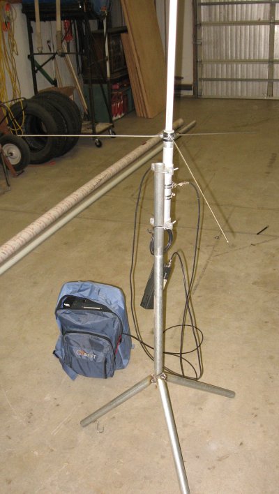
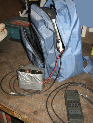
Build up a portable "station". This will consist of a good station antenna (hopefully) a way to mount it to the ground in the form of a tri-pod. Then you'll need a signal generator, an iso-"tee", some connectors and coax and a "test" receiver. For this experiment the Author used a "portable" sig. gen. a home built tri-pod, with a quick release antenna mount, for grabbing and walking around the suspect area of interference. The test receiver is an Icom IC-2AT. You can substitute a 3AT or 4AT depending on which band you are working with. There are also many commercial portables that can be crystaled or programmed on the frequency of interference. Put it all together in a single unit, powered by a couple of 6 volt lantern batteries. Shown here is the complete unit, with a back pack to carry the sig. gen. battery, and other cables.
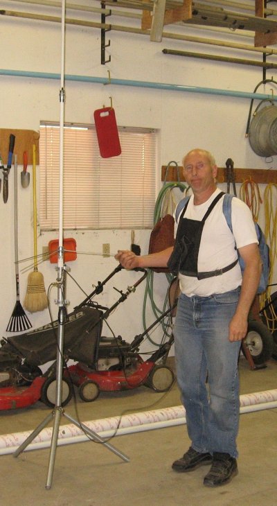
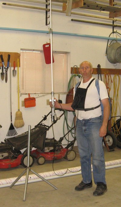
A nice touch is use of the chest pack to carry the portable "receiver" with its own spare battery. On the right shows a quick and handy way to pull off the antenna of the tri-pod for easy "walk-around" a suspect area.
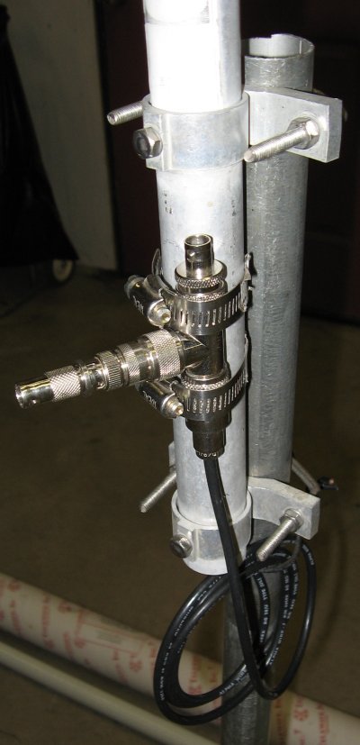
Close up of the antenna and isotee setup; just a few connectors held with a couple of hose clamps. The "tee" is made up from a normal Tee with the center pin removed. That will give around 40 dB of isolation from the sig. gen. to the receiver. You may want to carry a 50 ohm termination with the quick-release UHF connector to check site noise at the location you might have found the source of the noise for an accurate measurement. In place of the home-made Tee there are commercially made ones as well.