Home page
from TXRX Band-pass Cans
By John Haserick W1GPO

|
Antenna Index page Home page |
Making a 6-meter Duplexer from TXRX Band-pass Cans By John Haserick W1GPO |
|
Background:
Many of these band-pass cans were in paging service. The cans themselves come in 10 inch and 6.6 inch diameter and are about 80-82 inches long. The loops are the same for each diameter, and they can be re-bent. Four of these cans may be combined to make a very high performance band-pass/band-reject 6-meter duplexer, averaging -105dB notches with 1.2dB duplexer insertion loss. Their patented Vari-Notch configuration uses two N connectors per loop, so the notch circuit is actually in series, not off to the side as with other BP/BR duplexers, creating a notch depth at least 20 dB deeper than other duplexers for the same insertion loss.
The original TXRX cans were band-pass only, with two untuned coupling loops per can. I removed the original coupling loops, straightened out the two pieces of loop metal, and bent them into the same shape as an existing 6-meter Bp/Br loop. One new top plate for the Bp/Br loop was acquired, along with a variable capacitor, and utilized in each can. One of the original Bp top plates was capped off and put back into the top of the can to keep dirt and dust out. Four such cans were connected to form an excellent 6-meter duplexer with performance that rivals a six-cavity duplexer. This article documents the modifications and construction of the Bp/Br coupling loop assembly and the shortening of the can.
Can Modifications:
One advantage of these TXRX cans is that they will tune up to at least 56 MHz by just raising the resonator's Invar tuning rod. The rivets holding the can bottoms can easily be drilled out, before or after the can itself is shortened to 65 inches long. If sawing before removing the bottoms, first pull the Invar rod all the way up, or at least to 54 MHz, so no damage is done from sawing through the moveable lower section of the resonator. The Invar is easily cut with a hacksaw, and a new 1/4-20 thread for the knob can be created with a 1/4-20 die.
Coupling Loops:
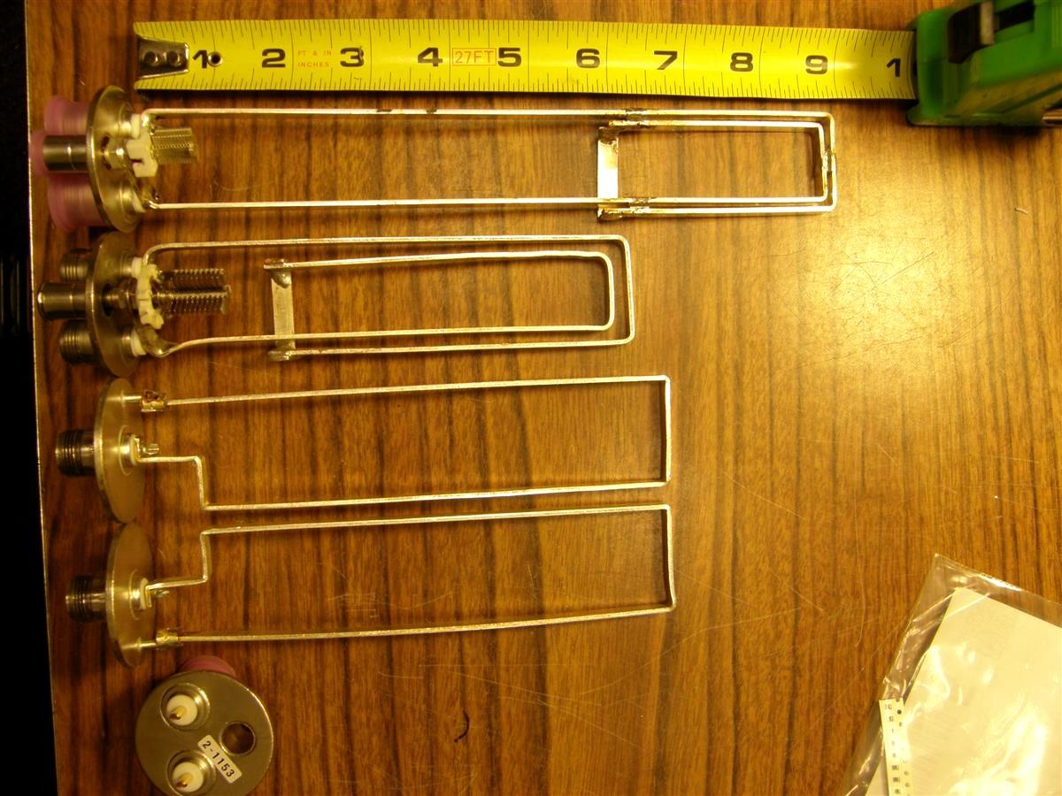
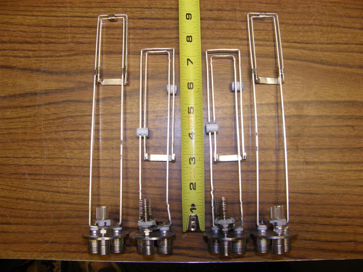
We recommend buying from TXRX, four new notch loop plate assemblies with the two N female connectors and 1/4 inch copper coupling attached (part # 2-1153, about $30 each), rather than making them from scratch. The single N connector loop plate remaining after the loop is removed can be capped by inserting a 5/16 inch metal hole plug, available from Home Depot, into the top of the bare N connector. Here's a photo showing, from top to bottom, a tape measure, a genuine TXRX Vari-Notch loop for 6 meters, one completed homemade loop, the two original band-pass loops, and a blank loop plate. Click on any photo for a larger view.
At least a 100W or larger soldering iron will be required. I recommend 96.5% tin, 3% silver, and 0.5% copper solder. The loops are made of silver-clad copper. Each new loop assembly will need a thick 1/4 inch ring terminal with the crimp removed to be soldered to the flat loop to hold the Hammarlund MAC20 or equivalent 20-22pF air variable capacitor. A Dremel tool with diamond disc is recommended to remove some of the porcelain on the capacitor so the assembly will fit inside if a MAC 20 is used. TXRX actually uses a smaller air variable cap with plates closer together (unknown voltage rating). A 3/8 inch metal hole cover from Home Depot works well to shield the 1/4 inch copper tube tuning openings over the variable capacitors.
A metal-clad 500V mica capacitor of about 10pF in parallel with the variable capacitor is recommended to make the notch tuning less touchy. The longer you make the loop, the less capacitance is required. The second loop was made longer than the first, so the 15pF mica shown was too high a value to tune a low side notch, but worked fine for the high side notch.
The length is not critical, but the second, longer one, even with the wrinkles from bending out the corners, is preferred. Just be certain there is enough left over loop to bend the short cross piece about 1/3 up the loop. Hemostats work great to hold the loop parts together before soldering. In fact all three sizes of loops worked with the same insertion loss and notch depth, the only difference is how close to the resonator they worked best, so there are slight differences in the amount of loop rotation for the same insertion loss and notch depth. The entire loop assembly can be purchased from TXRX for over $300 each, if home construction is not desired. It is part # 3-4453.
Note the horizontal strap on the longer second version loop is soldered to the right side of each descending loop, which should have been done on the first loop. Also note with the tuning tube facing the front, the outer loop is connected to left N center, and the right N, which also goes to the capacitor is part of the inner loop.
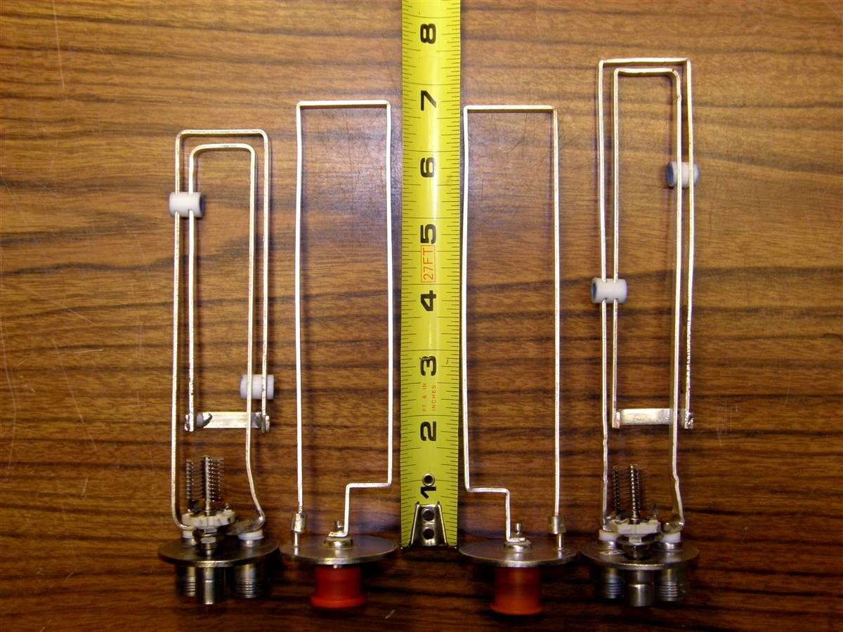
This loop design requires stabilization; otherwise the loop acts like a tuning fork, vibrating if the can is banged. We used two Teflon spacers made from 3/8 inch OD rod with a hole in the middle. Slots were cut to fit snugly over the loop wires. The outer holes were filled with Permatex Ultra Blue RTV (good to 500 degrees F) to anchor the insulator to the loop with no Permatex between the parallel loop wires. Here's a picture of the two loops with two Teflon insulators added to each next to two unmodified band-pass loops.
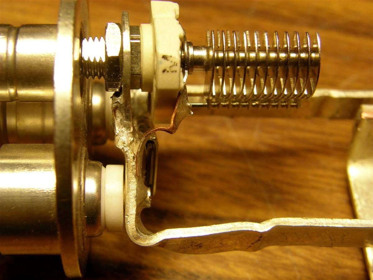
The now recommended method of fabrication is first straighten out the two bends that make the loop go horizontal about 1 inch from the bottom on one loop. This will become the new outer loop. We bent with smooth beaked pliers to almost get the loop straightened, then hammered more of the bend out with the loop against a piece of hardwood. Leave the bottom bent, because this will become the new bottom to fit over the N center pin (after adding a Teflon washer to the pin.) Both N connectors require a Teflon washer. The other loop becomes the inner loop after re-bending. Straighten out the small flange at the bottom of this loop as this is where the ring connector solders to the loop's top side at this spot. Remove about 1-3/4 inches from the other straight end of this loop for the horizontal strap. The strap will be higher than pictured, but this is probably better.
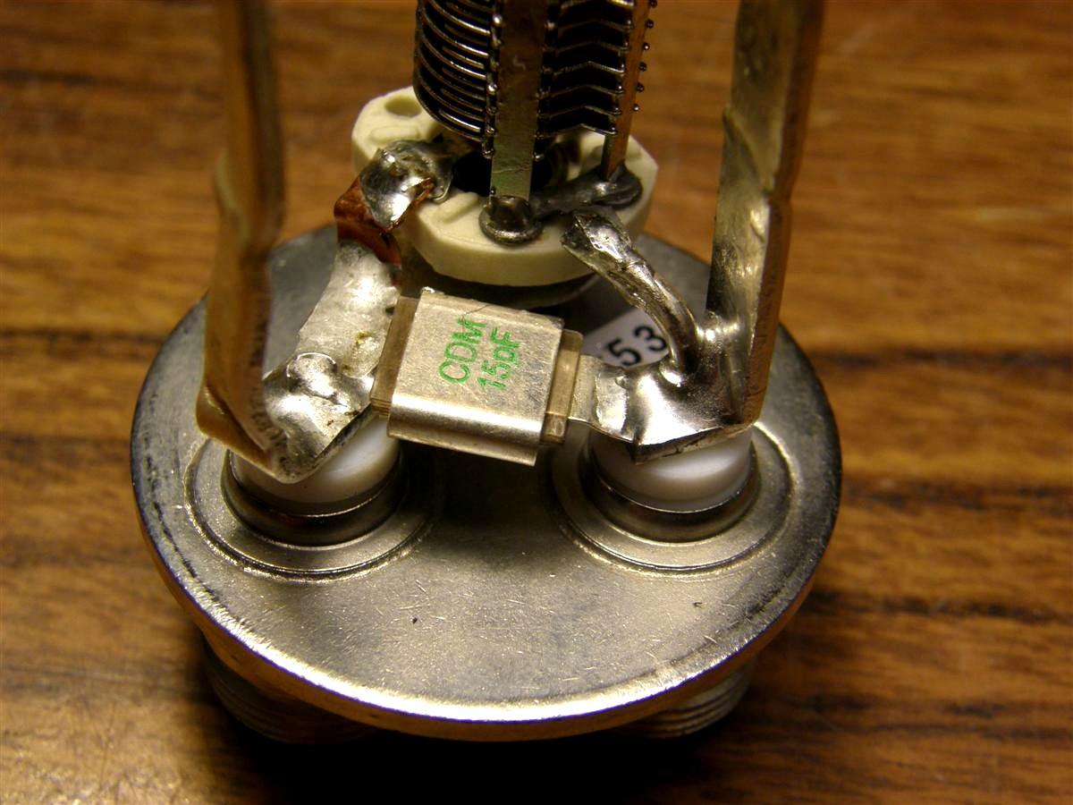
Here's a close-up picture of the capacitor area. Note the extra Teflon washers (TXRX part # 8-7359) between the Teflon on the N connector and the flat loop wire. We used some Teflon washers removed from a radio instead, for the same result.
This top view shows the TXRX on the left, and homemade loop on the right.

I actually did end up remaking one loop and modifying the other loop to match what was suggested in the article, with excellent results. See the photo below.
The two loops on the outside are stock TXRX 6m loops. The bottom of the cross-connecting loop is 2-3/4 inches above the loop plate. This cross piece is bent from a 1-3/4 inch piece of unused loop material taken off the end not connected to the N connector. Very importantly, the cross piece goes across the side of the loop opposite the air variable. With a 15 pF metal clad mica cap across the variable cap, and insertion loss set at 1 dB total for two connected cans, both high side and low side notches will now tune with less touchy adjustments. For these loops set up as described, the best compromise of notch depth vs notch width is for the coax length between the cans to be 13% less than a physical 1/4 wavelength, in other words, if the notch frequency is 52 MHz, the coax will be a 1/4 wavelength as measured with the test set-up, to have lowest SWR at 60 MHz.
Cabling:
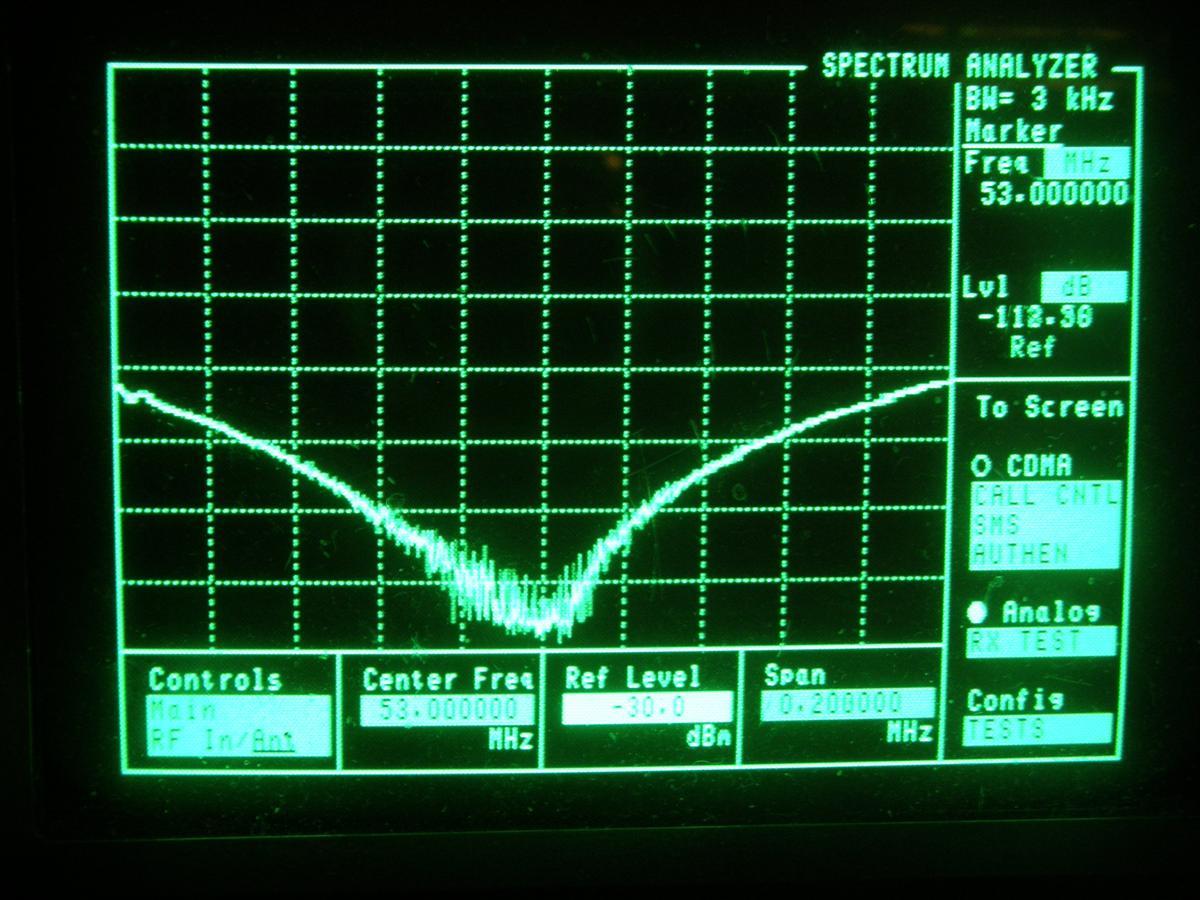
The coax cables going between the cans can be attached to either N connector. It is recommended that you make these 30% shorter than the calculated physical 1/4 wavelength if you are using the TXRX coupling loop dimensions, so the notch is wide enough so component frequency drift is not a problem. The greatest notch depth is achieved (over -115dB) with exactly 1/4 wavelength connecting coax, which gives the least coupling, but the bottom of the notch is only 20 kHz wide! See the spectrum analyzer trace below.
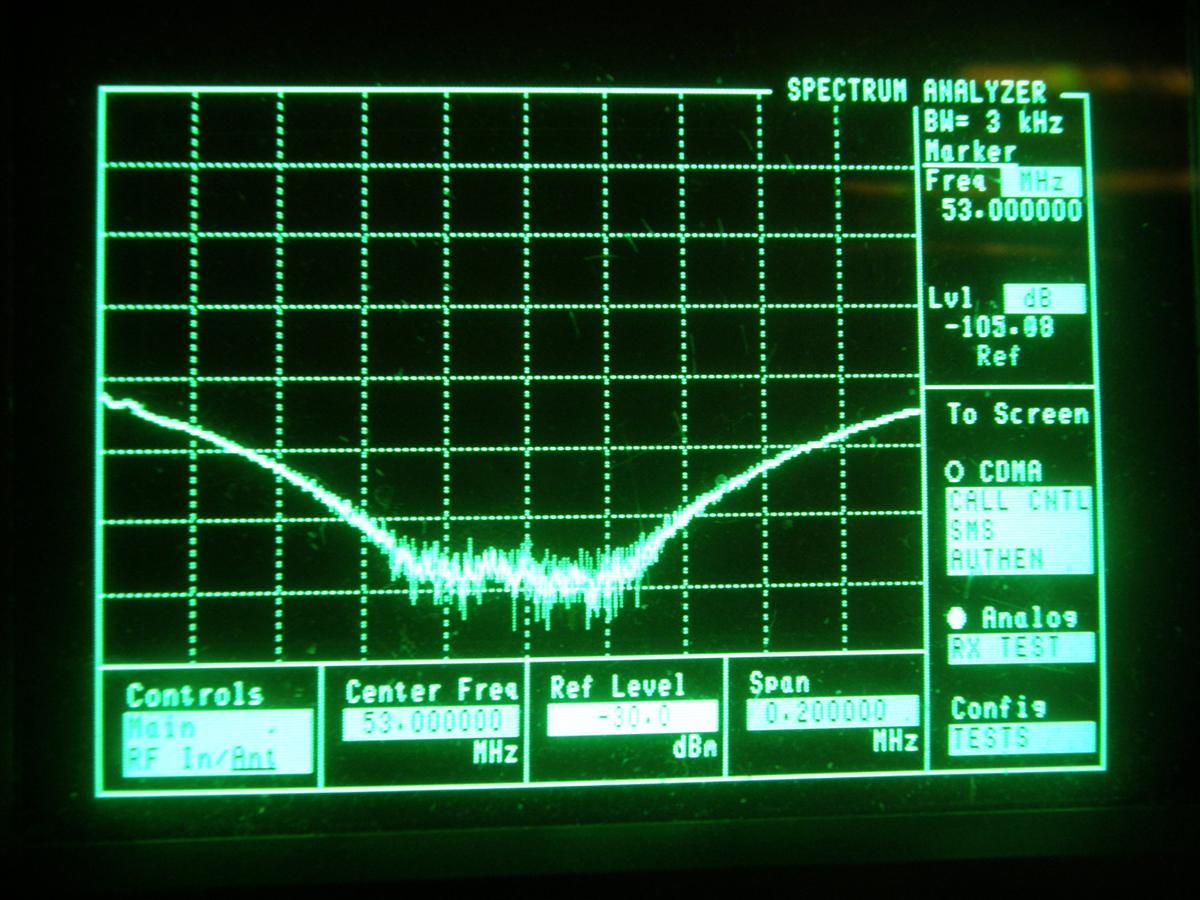
About 30% shorter coax gives a notch width of about 50-60 kHz and depth of -105dB for about 1.2dB of insertion loss using the TXRX coupling loop dimensions, a good compromise. See the wider spectrum analyzer trace below.
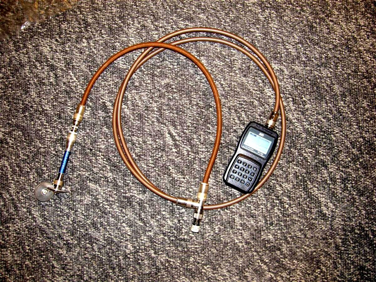
To test your coax electrical length, you can short one of the removed plate's N connectors with a strap between the center conductor and the plate, place your test cable with shorted far end, and hook it to a Teflon N Tee with one port going to an antenna analyzer and the third port to a good dummy load, as shown in the photo below. The frequency of lowest SWR or best RL is 1/4 wavelength. Here's a photo showing the test cabling.
Uh oh, here's the math. Squeamish readers can turn the other way. RG-214 coax has a Velocity Factor (Vf) of 0.66. At 53 MHz, 1/4 wavelength = 55.7 inches of electrical length. Multiply this by 0.66 (Vf) to get 36.77 inches of physical coax length. Now multiply this by 0.7 and you get 25.74 inches, which is close enough to 25.75 inches, the length TXRX specifies for their cables using their coupling loop dimensions. The 0.7 correction factor gets changed to 0.87 with my redesigned/shorter coupling loops.
The coax going to the antenna T connector needs to be 1/2 wavelength electrically between the can and the T, because the notch circuitry is at parallel resonance or high impedance at the opposite frequency of the can pass frequency, so on this opposite frequency is what the jumper is made 1/2 wavelength. This keeps the best SWR or return loss in line with the pass-band peak. We like to use 1/2 inch Superflex here. A good way to check this is to place an open N female from a plate with the loop removed on the far end, and the other end to the N tee with dummy load on the third port used to measure the 1/4 wavelength jumper, and read the frequency of lowest SWR or best RL.
TXRX uses RG-214 jumpers to the T, and cuts the coax to 72.3 inches for the 53.15 MHz high-side cans and 71.25 inches for the 52.15 low-side cans. Like with the inter-cavity cables, calculate the length using the Velocity Factor. Note that the CUT length is how long you cut the coaxial cable; it does not include the connectors. Each N-Male connector adds 1/2 inch of length to the cables. For confirmation, the 1/2 wave length for 53.15 MHz comes out to 73.33 inches, and when you subtract one inch for the two N-M connectors, you end up with a value of 72.33 inches, very close to the 72.3 inch CUT length specified by TXRX.
Tune-up and Performance:
You will need to use an insulated tuning tool or remove it after each attempt, because both of the capacitor's terminals are hot with RF and any metal in contact with the cap will affect the tuning. Follow the Bird/TXRX tune-up procedure in any Vari-Notch manual (available online), but first each loop needs to be individually rotated for the proper coupling so the best SWR or return loss co-insides with the center of the pass curve. As you decrease the coupling from critical coupling, the return loss gets progressively worse (the SWR goes up). Whatever that sweet spot is, we feel is the best amount of loss to set that can at. As a ballpark figure, TXRX suggests 0.6dB loss per can if using the 6.6 inch OD cans; the 10 inch cans should have less loss per can for the same 1 MHz split. Here's a photo of the top of one converted can.
Final performance specs for just two cans connected together (1/2 of the duplexer) using my shorter loops:
Final Notes:
The project is completed and I need to offer correction to pass loss on the TX side. Calculating the actual power in / power out of the duplexer instead of what turned out to be an erroneous reading from my HP8924C, it turned out there was no difference between the performance of the TXRX loops and the loops made from the pass cans, except the notch tuning is a lot less touchy with the reconstructed loops using parallel metal clad mica capacitors across the variable notch tuning capacitors. Also the resonator Teflon insulated spacers that were held in place with Permaseal Ultra Blue didn't work any better or worse than the stock nylon spacers, as one can still has its original nylon spacers.
This duplexer, because the 10-inch cans have a higher Q than the stock 6.6-inch TXRX duplexer, has better specs of:
53.29 Pass: IL: 0.95 dB, RL: 26 dB, 52.29 notch: -110 dB.
52.29 Pass: IL: 0.93 dB, RL: 26 dB, 53.29 notch: -108 dB.
It was important when getting the inter-can coax jumpers the exact length, to use a shorted Teflon insulated N female, preferably theTXRX N female left over from the bandpass loop, if going for deepest notch (these cans use less than 1/4 wavelength for increased notch width and less depth for less temperature effect, because it will be used in an unheated facility). Likewise for the 1/2 wavelength jumpers between cans and the antenna port Tee, use an open, disconnected TXRX N female and use the same Teflon N Tee connected to the analyzer that will be used in the completed duplexer.
In the photo below, the gold colored cans on the left are the converted 10-inch cans. The gold colored cans on the right are the existing TXRX 6.6-inch diameter can model 28-14-01 Vari-Notch duplexer. So far, the rebuilt TXRX is taking 265W, using the TXRX loops on the TX side, rebuilt loops on the RX side, even though TXRX rates their current 6m Vari-Notch for 250W max. The existing Vari-Notch in the picture has the older version loops with a spiral coil on one side, and handles 265W without a problem.

The cans are made with a 1/8-inch thick round Nylon spacer to stabilize the passband tuning assembly that was copied exactly. I came up with the idea to try a 1/4-inch thick Teflon spacer in the X configuration, which was more securing, but made no difference electrically. See the two photos below.
With the currently in-line but temporary 10-inch cans, the now Vari-Notch duplexer (Big Brother), there is 215W at the output into the feedline, whereas the existing was more lossy with 195W out. Most of the time, there's no desense with either set of cans.
Credits and Acknowledgements:
Thanks go to Jeff WN3A for the suggestion to use metal clad rather than 500v silver mica capacitors, which added about 5 db more notch depth per can.
Thanks go to Paul W1IMD for donating the 4 pass cans.
Clarke N1PAH cut the cans down to size.
Bob WA1MIK took the text, asked a lot of questions, and turned it into an article. He also added some text and math to further explain some items.
All photos were taken by the author.
Contact Information:
The author can be contacted at: jhaserick84 [ at ] comcast [ dot ] net.
Back to the top of the page
Back to Antenna Index page
Back to Home
This article created on Wednesday 19-Dec-2019
Article text and photographs © Copyright 2019 by John Haserick W1GPO.
Some text, layout, and conversion to HTML © Copyright 2019 by Robert W. Meister WA1MIK.
This web page, this web site, the information presented in and on its pages and in these modifications and conversions is © Copyrighted 1995 and (date of last update) by Kevin Custer W3KKC and multiple originating authors. All Rights Reserved, including that of paper and web publication elsewhere.