Home page
Ground Plane Antennas
By John Haserick W1GPO

|
Antenna Index page Home page |
Experimenting With 6 Meter Ground Plane Antennas By John Haserick W1GPO |
|
Background:
We have been experimenting with a number of 6 meter repeater antennas over the past 40 years, and would like to share what has been learned. Herb and Glenn Kreckman of Kreco Antennas have been very generous with parts, antennas, and advice on their coaxial dipoles. We have built several repeaters using the DB-212 side-mount dipoles and several with a special version of the ASP-600 ground-plane. The article includes photos of a special version Kreco Co-Plane, with excellent lightning protection, bandwidth, and mast decoupling with about the same gain as a 5/8 ground-plane, and a 3 dBd version of an ASP-600B (30-40 MHz) converted to a 6 meter 5/8 over 3/8 ground-plane.
Click on any photo for a larger view.
Duplexing off one antenna on 6 meters is more challenging than on the higher frequencies for several reasons:
Since most repeaters are not disconnected when an electrical storm is near, the tower ground, power line neutral ground, telephone, and cable grounds all need to be connected outside the building with probably at least #4 copper. I have also heard stories of the neutral being lost at the pole with the 120 volt lines still connected, so add a few good 10 ft ground rods at the service entrance for good measure, as no breaker box surge protector will protect against the loss of neutral!
Some 6M Antennas To Avoid For Duplexing:
Some Recommended Antennas For Duplexing:
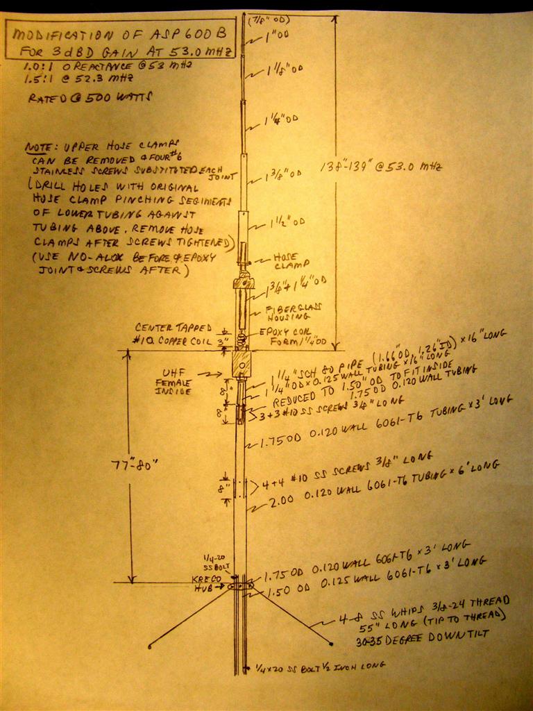
Converting The ASP-600 To 5/8 Over 3/8 GP For 6M:
The Antenna Specialists ASP-600 half wave to 5/8-wave ground-plane came in three frequency splits. The two most common were ASP-600B (30-40 MHz) and ASP-600C (42-54 MHz). On 6 meters it is more of a 1/2-wave ground-plane, so it has somewhat less gain than at 40 MHz.
It just happens to turn out that the ASP-600B coil is 1/4 wavelength on 6 meters, so it makes a great 5/8 over 3/8 center fed antenna with no modifications to the coil. The ASP-600C coil can be replaced by making a new one to be 1/4 wavelength. This requires a way to mount the antenna for tuning, a good antenna bridge showing reactance, and feed line close to odd multiples of 1/2 wavelength electrically for best tune-up.
We have converted three ASP-600Bs and one ASP-600C antenna. All outperformed any 5/8, 1/2, or 1/4-wave antenna, and have stood up to at least 1/2 inch of ice. The first one had two sets of four sloping radials, similar to the V6R. It was mounted at the top of a 100-foot tower. The site was high so it did have some coronal discharge desense, but no duplexing desense. We moved the lower four radials up to be between the upper set on the same hub, so now there are eight radials on the top hub. We had no change in field strength 25 miles away, and still no duplexing desense, so future versions just used one set of four or eight radials. The eight radials gave a little more bandwidth, with zero ohms reactance and 1.0:1 SWR at the resonant frequency.
This is not a good antenna to duplex from a house, unless it is at the 100-foot level, because the 60-degree downward secondary lobe, which is probably down about eight dB from the main lobe, would be aimed into household wiring. A better antenna would be the Dominator 5/8-wave, or Kreco Co-Plane at least 45 feet above the attic floor.
The ASP-600 is mounted on 1-1/4 inch pipe with NPT into the bottom of the base. The three horizontal ground plane radials are no longer attached to the base, but could be reused instead of the stainless steel whips attached to the whip hub from Kreco, which has #3/8-24 threads. Schedule 80 pipe is recommended, which can get quite heavy for possibly more than 10 feet, plus the threads can rust even with No-Alox, so we went with 6061 T6 aluminum from DX Engineering and Online Metals, had a machine shop reduce eight inches of the 6061 aluminum 1-1/4 pipe to fit inside the tubing, and Glenn at Kreco enlarge the hub to fit just over the tubing.
We used a drill and tap to make the threads to join the sections with screws and bolts.
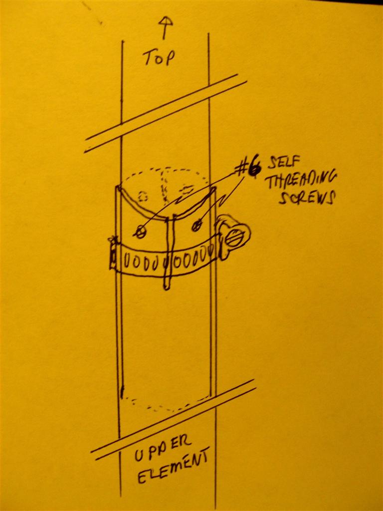
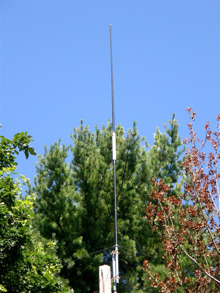
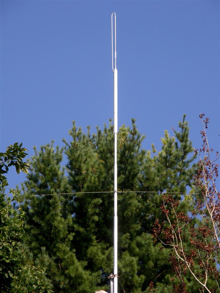
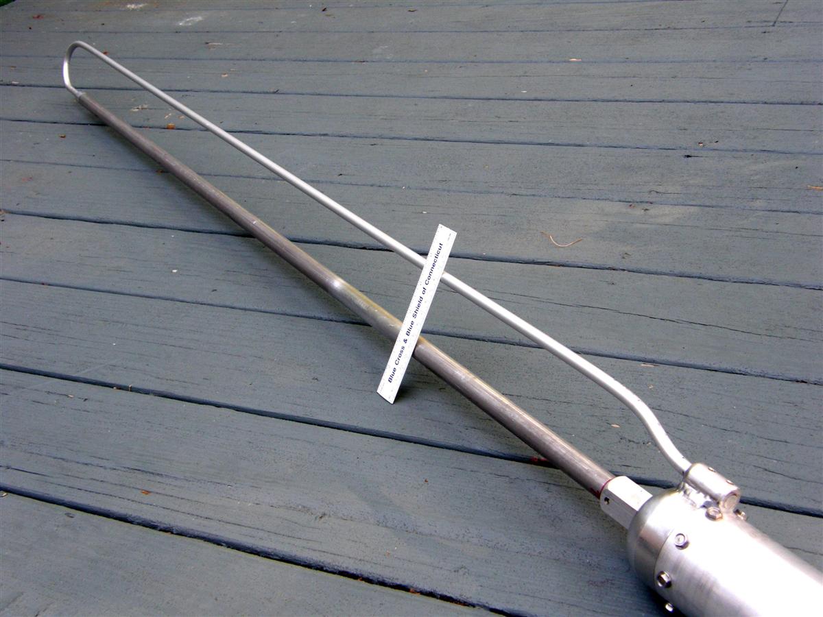
Here's a photo of the complete antenna without its whip radials. The upper element's upper hose clamps were replaced with screws, with Scotch 35 tape over the entire length. Grey tape might have been a better choice to blend better with the sky.
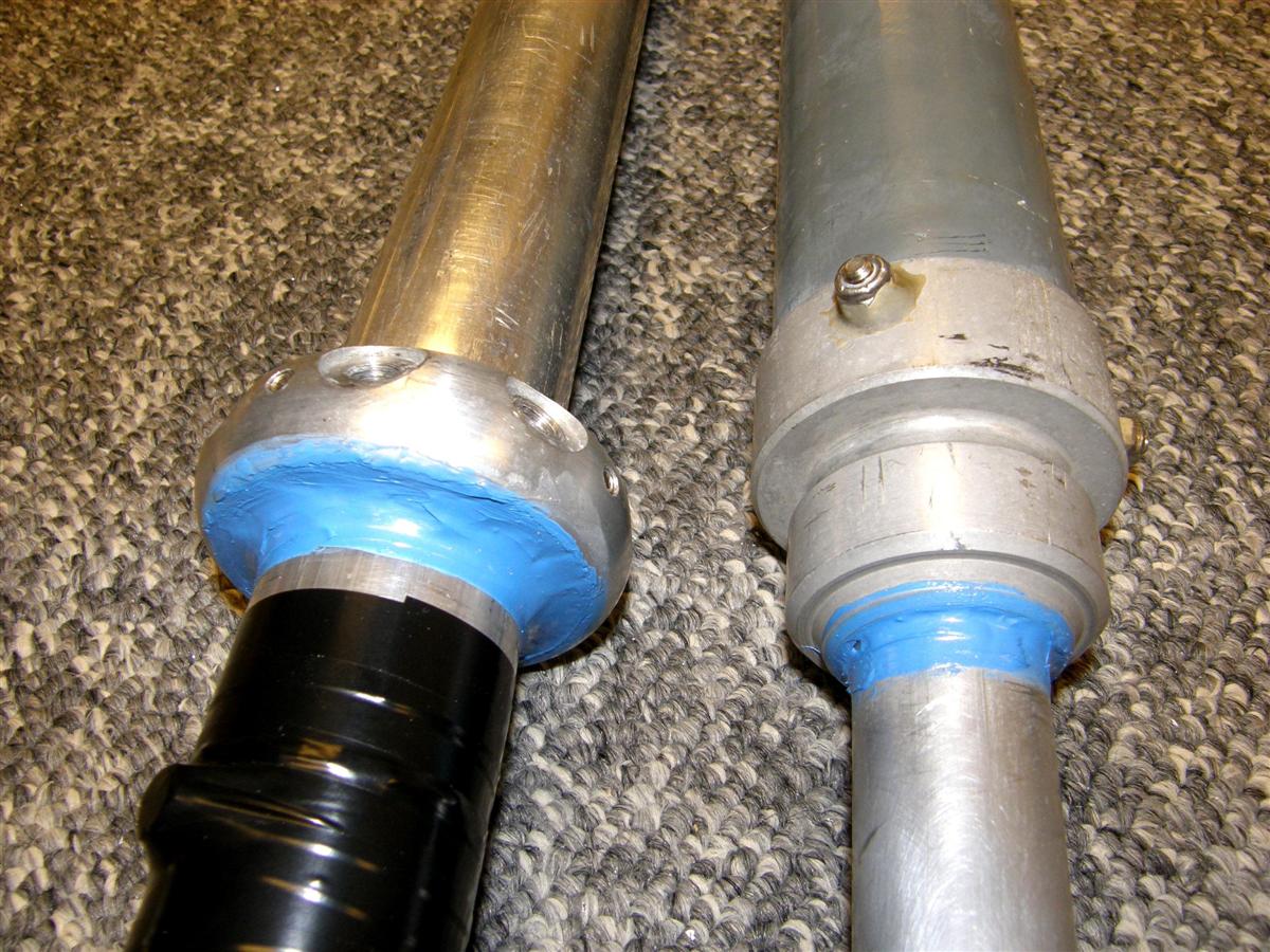
Aluminum 6061 T6 schedule 80 pipe is not quite strong enough at about 10 feet to support the antenna in high wind. Permatex Ultra Blue RTV silicone gasket maker (auto parts) is a superior sealer, where needed.
It is recommended to unscrew the top aluminum sealing ring on the fiberglass base coil assembly, remove the three bolts at the lower base portion just below where the radials went, and pull up the fiberglass housing to check the coil area for cleanliness. Clean and tighten the connection where the screw holds the coil to the aluminum tubing, add a tiny amount of No-Alox to just the aluminum-copper interface, then epoxy the cleaned, re-tightened joint.
Approximate substitute coil specs to convert the ASP-600C are about 50 inches #10 bare copper, 8-1/2 T, 1-3/4 inches OD, tapped at 3-3/4 T from bottom, coil length 2-1/2 inches.
Kreco Co-Plane Modification:
In comparison to the 1/4-wave monopole ground-plane, 1/2-wave coaxial dipoles have less 1.5:1 SWR bandwidth. This makes duplexing, with TX and RX frequencies one MHz apart, less efficient because of higher SWR. The Kreco shunt-fed 1/2-wave coaxial antennas are fed by an inductive loop between the inside of the skirt and the mast inside the skirt. This means a return element can be added as on the monopole ground-plane from the top down to the middle where the skirt starts. By making the space between the original element and new return element about the same as on the monopole ground-plane, SWR bandwidths become equal, because the coaxial skirts are already wide, and not the limiting factor.
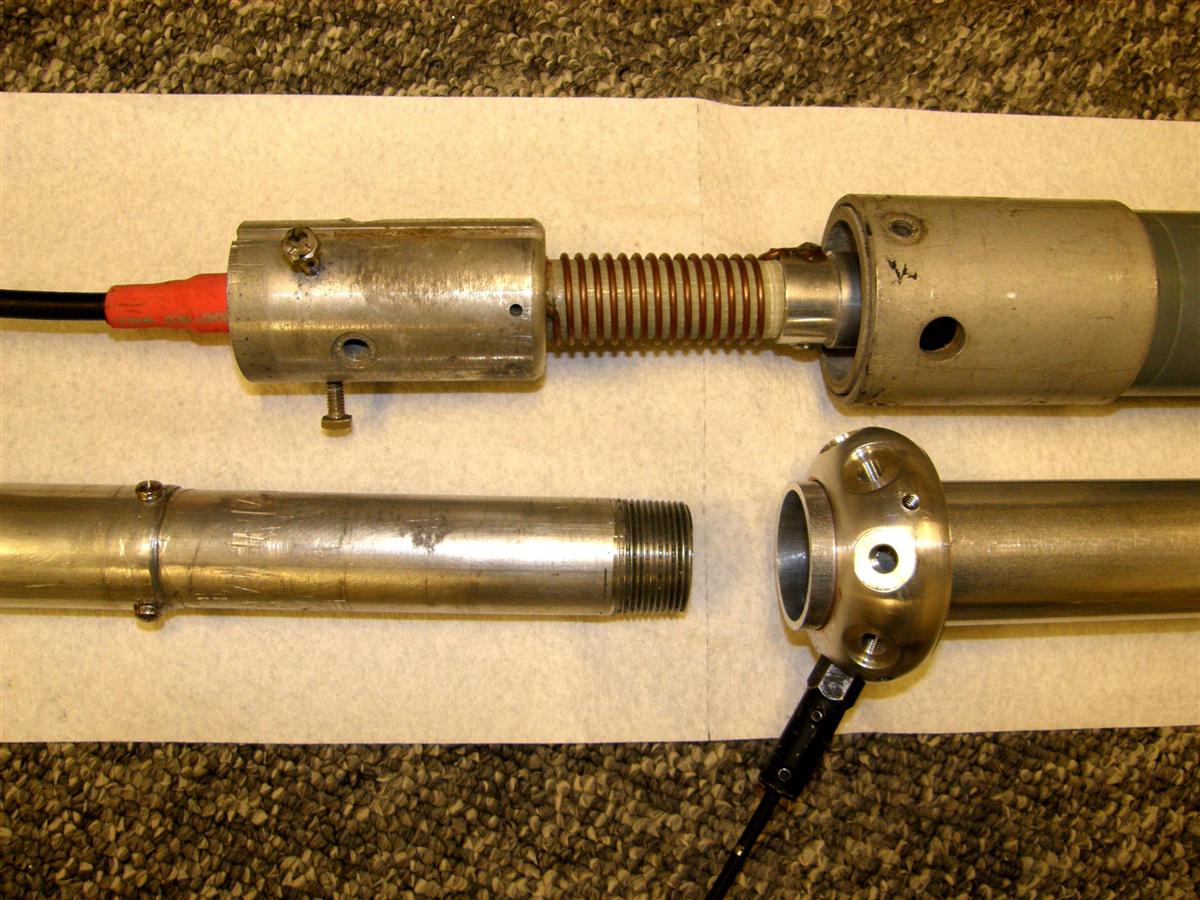
This photo shows the top element with the ferrule welded to a CP-41A antenna.
These two photos show the return element ferrule fastened to the narrower diameter skirt hub of a CO-35A antenna using three #10-24 screws, each 1 1/4 inches long.
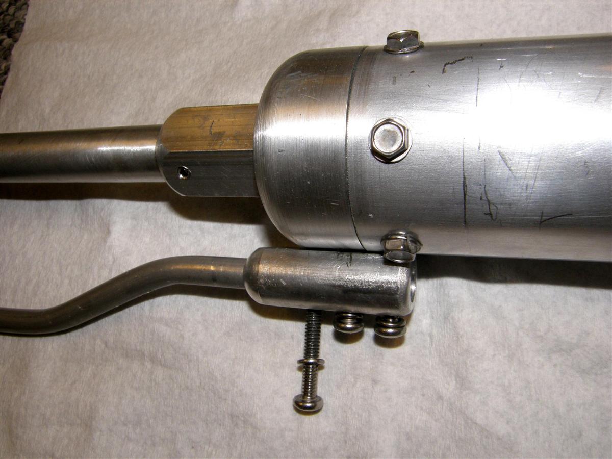
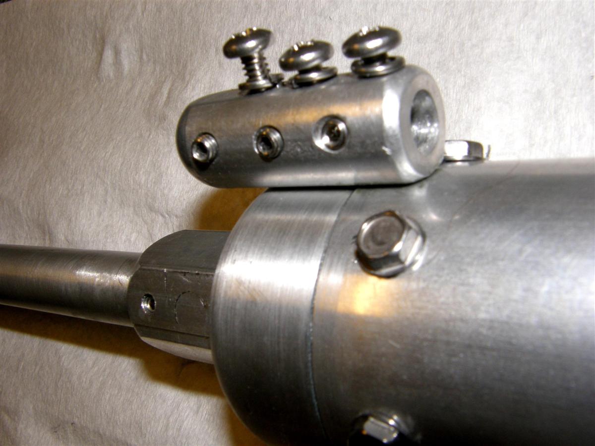
A new upper element and ferrule are required from Kreco. I do not recommend taking the easy way out and using the plated steel ferrule clip Kreco uses in their monopole ground-plane for duplexing, because a few years down the road, corrosion may set in, and "scratchies" may appear on the repeater. Instead, either weld or fasten with, say, #10-24 screws as shown. Welding is better, but this means taking the antenna apart. The problem with the screws is that the return loop length is not adjustable, as the holes go through the solid 3/8-inch return element rod. Note the two parallel flat edges, one against the antenna, and one for the screw heads. This was a CO-35A antenna. The mounted antenna picture shows a CO-41A with homemade extended mast made from 6061 T6 0.120-inch wall thickness telescoping tubing from DX Engineering, stainless set screw collar machined for #3/8-24 threaded stainless whips, and the extra return element with a welded ferrule. Performance was about same as the 5/8-wave Dominator ground-plane but unmatched lightning immunity, as we thought the first antenna was taken out by lightning (turned out to be the antenna to feed-line N connector suddenly developed an open center pin connection!).
Sirio 827 11-meter Ground Plane Modifications:
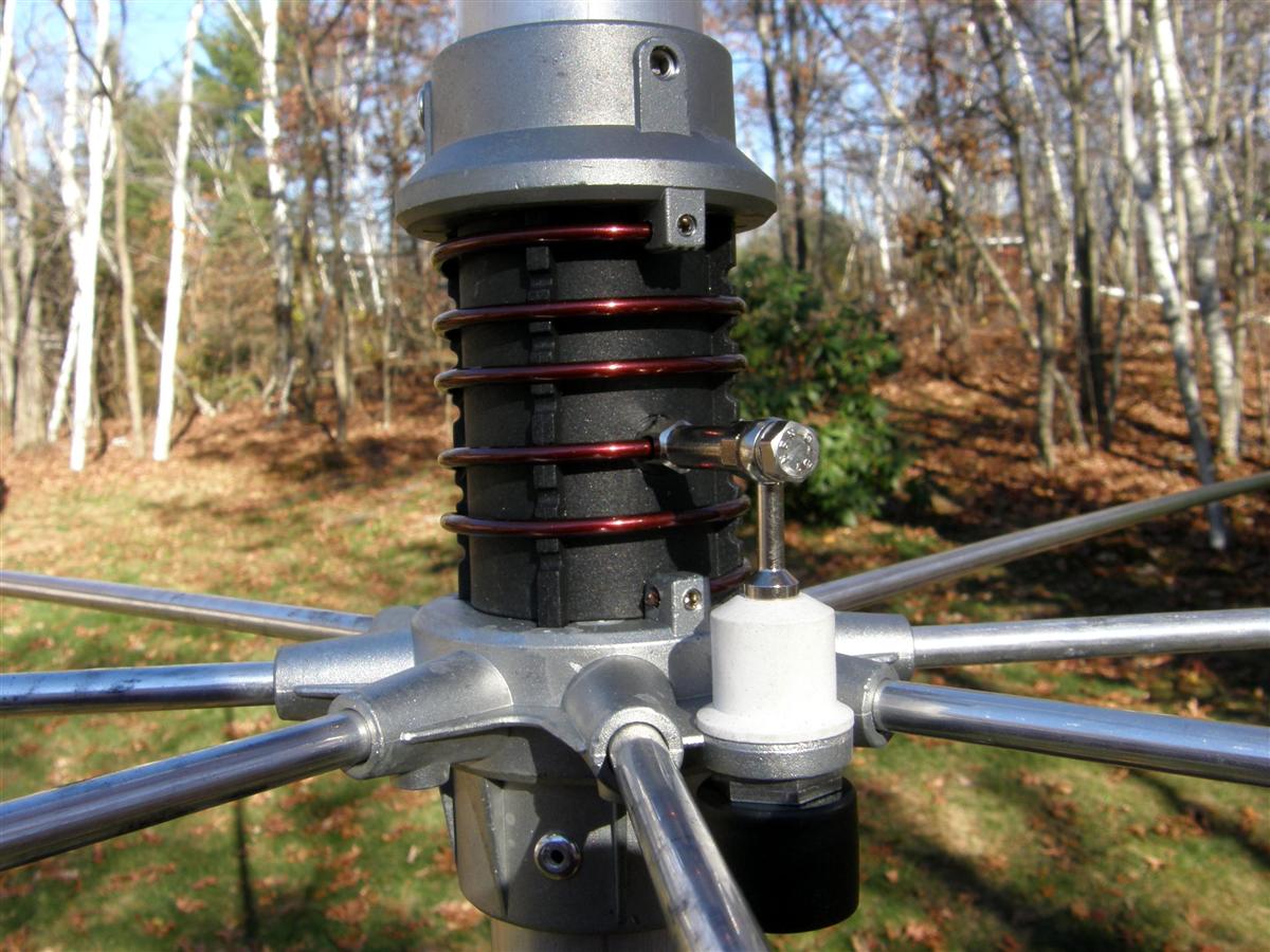
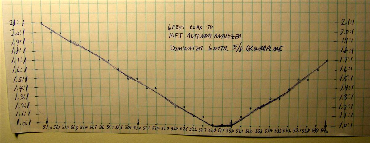
If the antenna is purchased say from Amazon or Wal-Mart and you do the conversion, it does save money for very little effort with the use of an antenna bridge/analyzer, plus it could be used for 10M without coil changes. For 6M, shorten the vertical element, and remove turns of the 10 gauge enameled wire to go from 10 turns tapped at 4 turns, to 5 turns tapped at 2 turns. This will turn it into a Dominator 6m antenna mentioned above. See the photo below of a 6M coil.
The SWR will go down to 1.0:1 at resonance with no reactance. See the VSWR graph below.
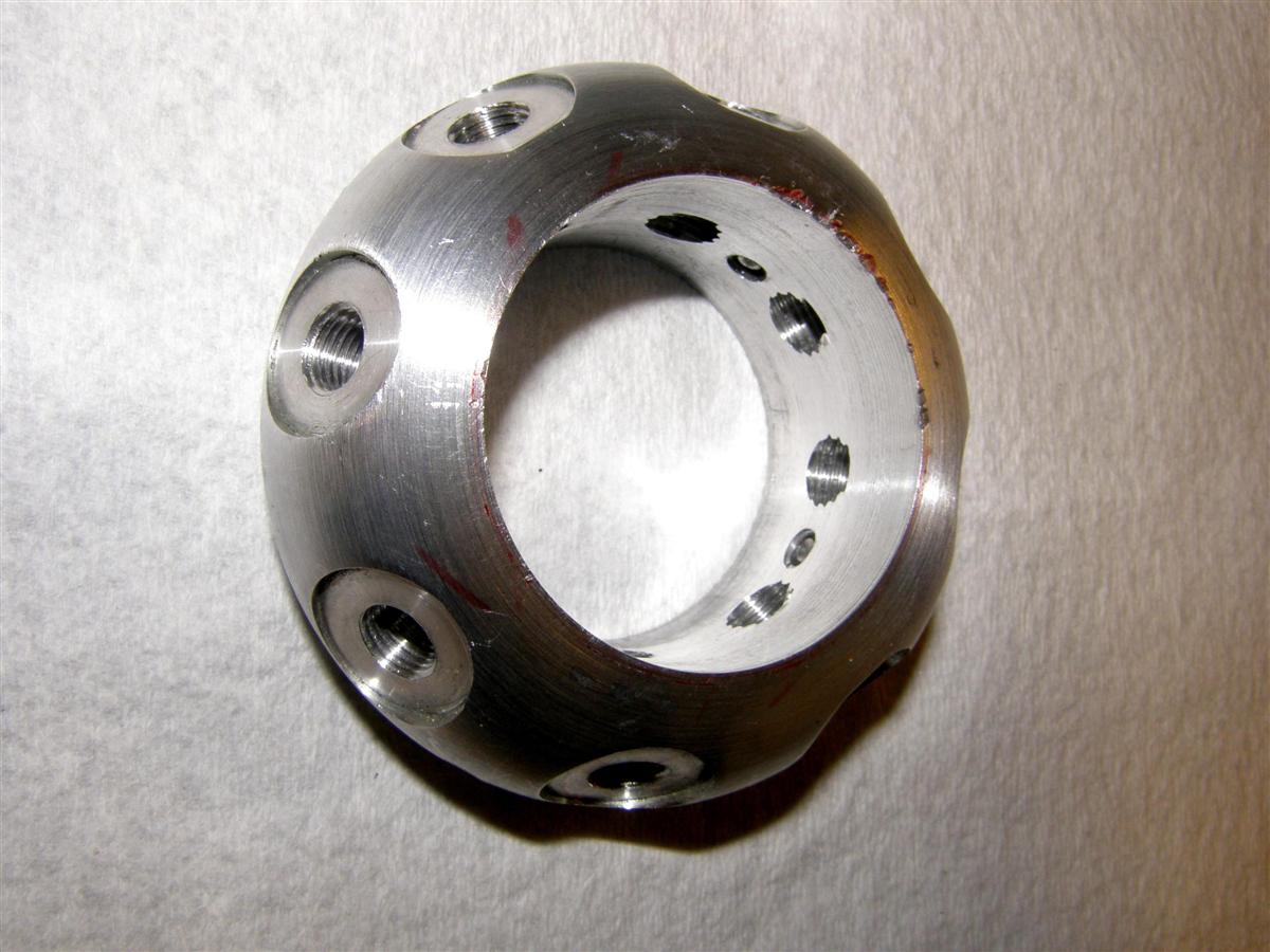
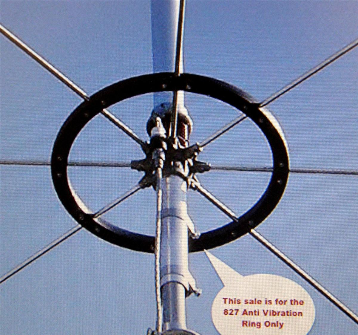
I recommend three split ferrites over the coax just below the antenna SO-239 connection, to take best advantage of the mast isolation provided by the extra four quarter wavelength radials. All tubing is metric. The vertical radiator is plenty strong for most sites, but the radials could be damaged by ice loading, so the nylon anti-vibration ring is a good idea. See photo below of such a ring.
Even with this ring, the antenna radials are still not up to the strength of say a DB or Celwave 1/4 wave monopole ground-plane. However, this 5/8 ground-plane, on 6 meters, should have 3.4 dB more gain than a monopole ground-plane. Rain has no effect on SWR.
Conclusions:
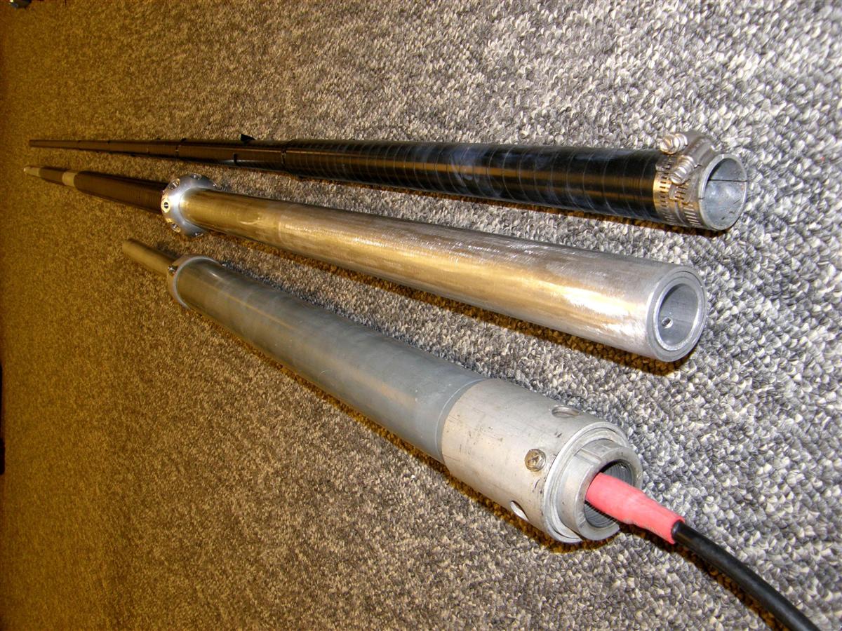
This has been one of my most intense interests for years, most of which knowledge I have learned by trial and error by friends and myself. In fact, I just finished work on a 1/2 over 1/2 over 1/4-wave ground-plane that did not work as expected, but I learned most likely why, and in the process discovered a new way of increasing decoupling of a coaxial dipole to the mast. After a lot of work we ended up with just one very well decoupled 100% efficient dipole, and could not do a three-section collinear vertical with 3 dBd gain as planned. Here is a picture of the only partially working monstrosity 26 feet long that is now 21 feet.
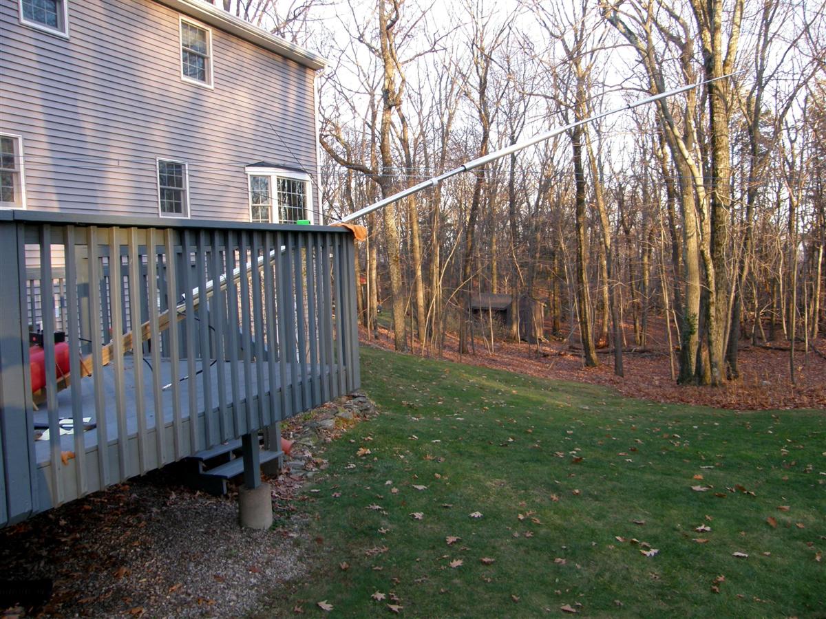
It turned out that the middle dipole could not be made to resonate and at the same time tune out reactance introduced to the top dipole, so the top portion of the middle dipole had to be shortened 10 inches from a 1/4 wave for the top dipole to have zero ohms reactance at resonance, and that made the middle dipole an extremely effective choke to make the mast invisible to the antenna (in my mind). The bottom 1/4 wave ground-plane was eliminated cause no RF was getting to it. So the antenna is now down to a true 0 dBd after all that work and expense, but has excellent lightning protection, because it is fed by a 13-inch loop between the skirt and mast with the coax inside the mast (Kreco shunt fed coaxial)!
Contact Information:
The author can be contacted at: jhaserick84 [ at ] comcast [ dot ] net.
Back to the top of the page
Back to Antenna Index page
Back to Home
This article created on Sunday 29-Nov-2015
Article text and photographs © Copyright 2015 by John Haserick W1GPO.
Layout and conversion to HTML © Copyright 2015 by Robert W. Meister WA1MIK.
This web page, this web site, the information presented in and on its pages and in these modifications and conversions is © Copyrighted 1995 and (date of last update) by Kevin Custer W3KKC and multiple originating authors. All Rights Reserved, including that of paper and web publication elsewhere.